
Why this matters
A graphics card in a workstation can be fast, cool or quiet, but it cannot be all three at full measure. Most computers settle the matter with fan curves chosen by feel. We want our own controller, part of WS.Sensor in WS.Remote, to settle it with evidence: to keep the card at full speed and inside its safe limits, and to make no more noise than the moment requires. For that the controller must know, for any fan setting and any power, how hot the card will get and how quickly. This article describes how we measured that, how we turned the measurements into a model, and how we tested the model before trusting it with a real machine.
Abstract
We measured the core and memory temperatures of a GeForce RTX 5090 at fixed power limits, from 575 down to 402 W, as a function of the GPU fan speed and the case fan speed. Intake air stayed between 18.7 and 19.8 °C over both days. The case had three 120 mm intake fans at the front, blowing across the motherboard and the graphics card about 3 to 5 mm from its edge, and one rear exhaust fan; the top was open. The small 92 mm fan by the power supply was left on its own setting and not counted.
The first run took about 5.6 hours: a 41-minute pilot, a 98-minute fan grid and a 3.25-hour power-limit run. On 21 October about 4.7 hours more followed: a morning series, a manual series, a 112-point second run over case fans, GPU fans and power limit, and a repeat of its slowest points. After a fan change the temperature settles exponentially with a time constant of about 50 s. After 20 s only a third of the change has happened; a plain reading is reliable only after about 3τ, some 2.5 minutes.
In the first run a normal cell therefore took 70 s: 10 s discarded after the change, 60 s logged, and a first-order fit to find the settled value. For the hot spot this matched the settled value within 0.5 °C on average; the core and memory, read in whole degrees, still need cells run to steady state.
Status. Results from one GeForce RTX 5090 in a case with an open top are in: a fan grid at 575 W, power-limit runs down to 400 and 402 W, a second run over case fans, GPU fans and power limit, and static and dynamic models of the core. The quietest-settings table, the closed case and two cards follow.
Key findings
- The card’s own fans dominate. Each 1000 rpm more on the GPU fans lowered the core by 7.6 °C and the memory by 7.3 °C; the case fans by 0.66 and 0.71 °C (575 W, top open; 60-second means, likely underestimates). At low GPU fan speed the case fans matter more: in the second run, with the GPU fans at 40 %, case fans at 2920 instead of 1000 rpm lowered the core by 9.0 and the memory by 9.6 °C at 575 W. From 70 % GPU fans up the difference was 2 °C or less on the core (518 to 402 W). Core and memory, second run
- One equation for the core. In the second run a single resistance equation with five constants reproduced the core at the 88 same-day points of the final table, case fans, GPU fans and power limit together, with an RMSE of 0.83 °C; its 10 °C offset came from unsettled points, and settled checks put it at about 0 to 3 °C. A dynamic model with one thermal mass, fitted to the 1 Hz logs, predicted daytime runs it had not seen within about 1 °C, and 20 settled points within 0.67 °C. Core model, dynamic model On the settled points of 4 sessions, the two-path model (11) fits within 0.37 °C (leave-one-out 0.52 °C). Statistical tests
- At full power the core is the binding limit. At 575 W the memory runs 6.4 to 9.4 °C above the core, so with our 100 °C memory limit the core reaches its 90 °C maximum first. At 402 W the gap grows to 11.9 to 13.5 °C, and the memory limit can bind first. Memory temperature
- Power limit. At fixed fans, each 100 W less lowered the hot spot by about 8 to 13 °C. The slopes are approximate until a steady-state rerun. The card accepts no limit below 400 W, 70 % of stock. From 575 to 402 W, with the GPU fans at 40 % where both ends are settled, the core fell by 12.5 to 13.4 °C and the memory by 8.0 to 9.0 °C; over the whole second-run table the falls range from 9.7 to 16.4 °C and 4.0 to 13.3 °C. Power limit, second run
- Readings need time. The median hot-spot time constant is 50 s: a reading 10 to 20 s after a fan change shows only 18 to 33 % of the change. A 60-second fit matched the settled hot spot within 0.5 °C on average; core and memory need settled cells. In the second run, 60 seconds was enough only after a small falling step of the power limit; after a large step a point needs about five minutes to come within 1 °C. Settling, how long a point needs
- Limits. RTX 5090 core: maximum operating 90 °C, slowdown 93 °C, shutdown 96 °C. Memory: no official GDDR7 limit is published; we use a derived working limit of 100 °C junction temperature. Table by generation
- Repeatable within a run. The reference cell held within 0.3 °C over a night; between runs, fast cells differed by up to 4 °C. Both days took about 10.3 hours and about 4.8 kWh for the card: 5.6 hours and 2.75 kWh on the first run, 4.7 hours and 2.1 kWh on 21 October.
The problem
A GeForce RTX 5090 is rated at 575 W of total graphics power [1]. In a workstation that heat leaves through two sets of fans: the card’s own and the case fans. More airflow lowers temperatures and raises noise.
Most systems settle this trade-off with fan curves chosen by feel; we measure it instead. We look for the pair of fan speeds that holds a target temperature with the least noise. We also look for the highest power the card can draw within a noise budget.
The answers differ between an open and a closed case, so we measure both.
What we measure
Two inputs are set by the test, one condition is measured but not controlled, and the rest are the card’s response.
| Symbol | Quantity | Role |
|---|---|---|
| GPU fan speed, rpm | input, set by the test | |
| case fan speed, rpm | input, set by the test | |
| intake air temperature, measured in the bottom chamber of the case, °C | disturbance, measured | |
| GPU core temperature, °C | output | |
| memory temperature, °C | output | |
| hot-spot temperature, °C | output | |
| board power, W | held steady by the load | |
| sound pressure level at the operator position, dB(A) | output |
Fan speeds are set as duty cycles, but the model uses the measured rpm. The relation between duty and rpm is not linear and differs from fan to fan.
The GeForce RTX 50 series does not report a hot-spot temperature through the public driver interface. We read it from the GPU’s on-die thermal registers.
Temperature limits
NVIDIA lists a maximum GPU temperature of 90 °C for the GeForce RTX 5090 [T1]. In the driver this is the maximum operating temperature, where clocks start to fall [T9]. The driver of our card also reports a slowdown threshold of 93 °C and a shutdown threshold of 96 °C.
The 90 °C figure is not new: the RTX 4090 is listed at 90 °C too [T2]. The drivers also report a lower target temperature for fan control, 83 °C on the RTX 3090 and 3090 Ti [T6]; it is not the maximum.
For the memory NVIDIA publishes no limit, and Samsung gives no temperature range for the GDDR7 part used on the RTX 5090 [T13]. A distributor lists the part at 0 to 95 °C operating, without saying whether this is case or junction temperature [T19]. On the Founders Edition all 16 GDDR7 packages sit on the front of the board, around the GPU and under the main cooler [T14][T15]. In our measurements the case fans change the memory temperature far less than the card’s own fans (Figure 5), except at low GPU fan speed (second run). What the memory reading is, and the limit we use.
We work to two limits: the core never above 90 °C, and the memory junction at most 100 °C, a working limit we derive below. The first night used a stricter memory limit of 88 °C. During a test the core stops earlier, 5 °C below the slowdown threshold.
| Card | Generation | Max operating (core) | Slowdown / shutdown | Memory | Memory limit |
|---|---|---|---|---|---|
| GeForce RTX 2080 Ti | Turing | 89 °C [T4] | 91 °C* [T7] / 94 °C* [T7] | GDDR6 | Tc 0–95 °C [T10]; Tj not published |
| GeForce RTX 3090 | Ampere | 93 °C [T3] | 95 °C* [T6] / 98 °C* [T6] | GDDR6X | about 110 °C Tj, reported [T12] |
| GeForce RTX 3090 Ti | Ampere | 92 °C [T3] | 94 °C* [T6] / 97 °C* [T6] | GDDR6X | about 110 °C Tj, reported [T12] |
| GeForce RTX 4090 | Ada Lovelace | 90 °C [T2] | not published | GDDR6X | Tc 0–95 °C [T11]; about 110 °C Tj, reported [T12] |
| GeForce RTX 5090 | Blackwell | 90 °C [T1] | 93 / 96 °C, our card | GDDR7 | not published [T13]; 95 °C listed by a distributor, case or junction not stated [T19]; we use 100 °C junction, derived |
| RTX A6000 | Ampere | not published; 93 °C* [T8] | 95 °C* [T8] / 98 °C* [T8] | GDDR6 ECC [T16] | not published |
| RTX 6000 Ada | Ada Lovelace | not published [T17] | not published | GDDR6 ECC [T17] | not published |
| RTX PRO 6000 Blackwell | Blackwell | not published [T18] | not published | GDDR7 ECC [T18] | not published |
Max operating: NVIDIA’s published maximum GPU temperature. Slowdown and shutdown are not published by NVIDIA; values marked * come from driver reports of single cards. Tc: case temperature; Tj: junction temperature.
- T1. NVIDIA. GeForce RTX 5090 specifications. nvidia.com
- T2. NVIDIA. GeForce RTX 4090 specifications. nvidia.com
- T3. NVIDIA. GeForce RTX 3090 and 3090 Ti specifications. nvidia.com
- T4. NVIDIA. GeForce RTX 20 series comparison. nvidia.com
- T5. NVIDIA. GeForce RTX 50 series comparison. nvidia.com
- T6. NVIDIA Developer Forums. Driver report for the RTX 3090 and 3090 Ti, single cards. forums.developer.nvidia.com
- T7. NVIDIA Developer Forums. Driver report for the RTX 2080 Ti, single card. forums.developer.nvidia.com
- T8. NVIDIA Developer Forums. Driver report for an RTX A6000, quoted for comparison in a thread on the RTX 6000 Ada. forums.developer.nvidia.com
- T9. NVIDIA. System Management Interface documentation: definitions of the temperature thresholds. docs.nvidia.com
- T10. Micron MT61K256M32JE-14:A, GDDR6 8 Gb, case temperature 0–95 °C (distributor listing). digikey.com
- T11. Micron MT61K512M32KPA-21:U, GDDR6X 16 Gb, case temperature 0–95 °C (distributor listing). digikey.com
- T12. Igor’s Lab. RTX 3090 Founders Edition water block test: GDDR6X junction limit of 110 °C (secondary source). igorslab.de
- T13. Samsung Semiconductor. K4VAF325ZC-SC28 GDDR7: no temperature range given. semiconductor.samsung.com
- T14. PCGamesN. The GeForce RTX 5090 board: all GDDR7 on the front, around the GPU. pcgamesn.com
- T15. Igor’s Lab. GeForce RTX 50 GDDR7 temperature zones: 16 memory packages on the RTX 5090. igorslab.de
- T16. NVIDIA. RTX A6000 specifications. nvidia.com
- T17. NVIDIA. RTX 6000 Ada Generation specifications. nvidia.com
- T18. NVIDIA. RTX PRO 6000 Blackwell specifications. nvidia.com
- T19. Fusion Worldwide. Catalogue entry for the Samsung K4VAF325ZC-SC28: maximum operating temperature 95 °C, case or junction not stated; retrieved 21 October 2026. fusionww.com
- T20. PC Games Hardware, 1 February 2021: the memory junction reading is the highest of all memory temperatures inside the silicon, and throttling starts at about 110 °C on GDDR6X (statements by the developer of a monitoring tool). pcgameshardware.de
- T21. Guru3D. Samsung is the primary supplier of GDDR7 memory for GeForce RTX 50 GPUs. guru3d.com
- T22. Alktech. Review of the MSI GeForce RTX 5090 32G Suprim Liquid SOC: memory junction 68–74 °C in a 4K benchmark, about 546 W, about 28 °C room air. alktech.co
- T23. Igor’s Lab, 21 July 2026. RTX 50 modders unlock per-module temperatures for GDDR7: eight readings on the RTX 5090, apparently for paired packages. igorslab.de
What the memory temperature is, and which limit we use
The memory reading is the memory junction temperature: one value per card, reported by the driver. Monitoring tools show it as the memory junction temperature; their developer describes it as the highest of all memory temperatures inside the silicon, not a surface or average value [T20]. NVIDIA does not document how the value is formed.
Over 33 of the 34 grid cells the memory sat 6.4 to 8.5 °C above the core, 7.3 °C on average. The remaining cell, the first of the night with every fan at 100 %, read 9.4 °C while the card was still warming up. Core and memory moved together, with a correlation of 0.988, and the gap showed no consistent trend with either set of fans. Part of its scatter of about ±1 °C comes from the memory reading, which is often in whole degrees.
Neither NVIDIA nor Samsung, the main GDDR7 supplier for the RTX 50 series [T21], publishes a junction limit for GDDR7. Higher figures quoted online cite no datasheet. The 95 °C distributor figure [T19] does not say whether it is a case or a junction temperature, and a case limit is not directly comparable with a junction reading. For comparison, GDDR6X on RTX 30 cards throttles at about 110 °C junction, according to the developer of a widely used monitoring tool; Micron and NVIDIA do not publish it in public documents [T12][T20].
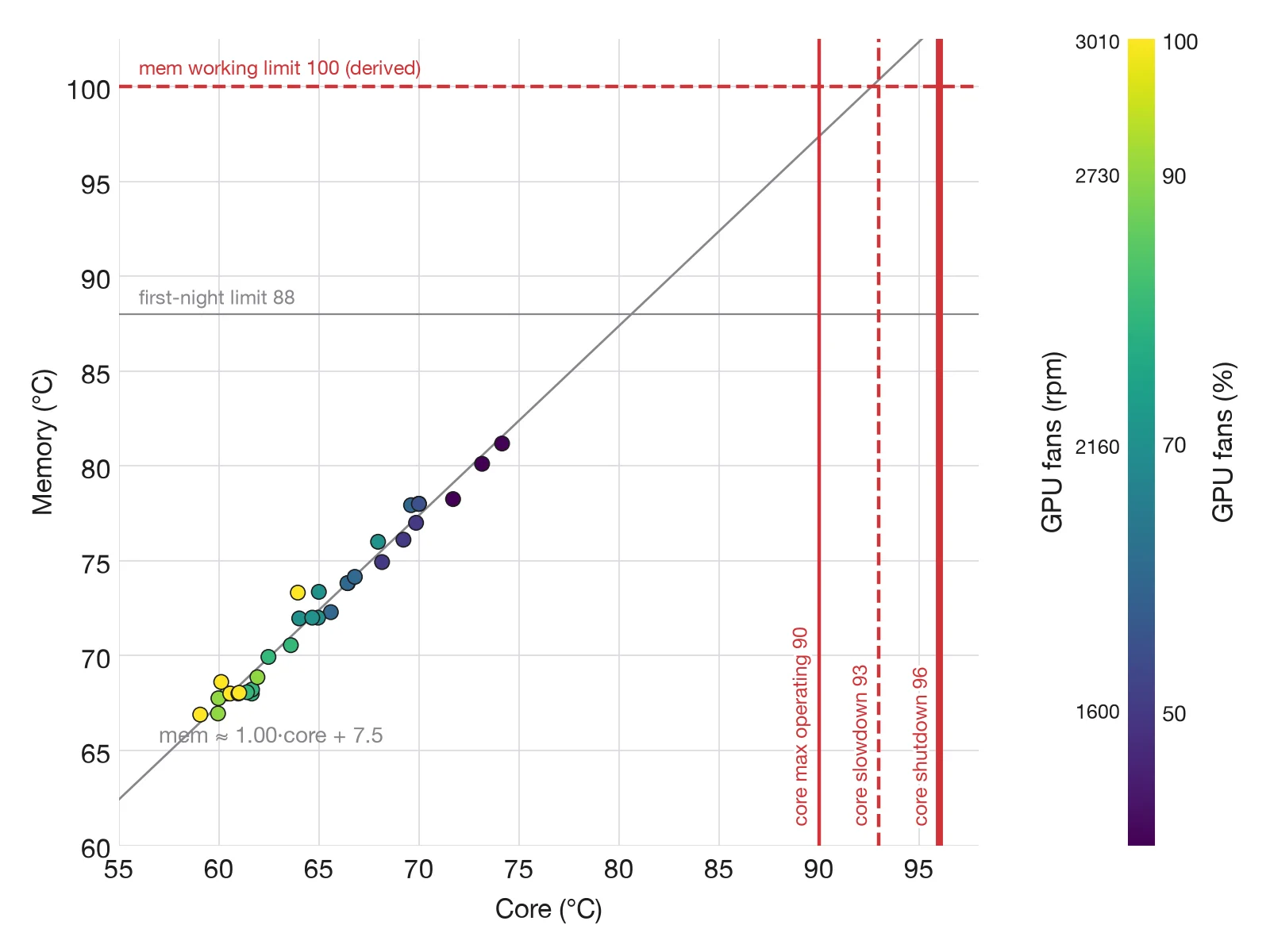
We therefore use a derived working limit of 100 °C memory junction temperature. It is our own limit, not a manufacturer rating. At 575 W the memory ran 6.4 to 9.4 °C above the core over both runs, so at a core of 90 °C it would read at most about 99.4 °C: at full power the core’s 90 °C binds first, narrowly. At lower power limits the gap widens. In the second run it was 8.0 to 10.1 °C at 518 W, 9.9 to 12.1 °C at 460 W and 11.9 to 13.5 °C at 402 W. There the memory reaches 100 °C while the core is at about 86.5 to 88 °C, so with a reduced power limit and slow fans, the case of Power within a noise budget, the memory limit binds first. Equation (14) therefore takes the smaller margin of the two. The gaps were measured with this load and an open top; a closed case may change them.
The first night ran with a stricter memory limit of 88 °C. Together with the hot-spot limit, it is why cells with GPU fans at 40 to 50 % and the two slowest case speeds are missing.
Others report similar values. A review of a liquid-cooled MSI RTX 5090 measured a memory junction temperature of 68 to 74 °C in a 4K game benchmark at about 546 W and 28 °C room air [T22]; our cells, at a constant 575 W and 19 °C intake, read 67 to 81 °C. Modders have also unlocked more detailed memory readings on RTX 50 cards: eight on the RTX 5090, apparently one per pair of packages [T15][T23]. We may read these with our own code in a later run.
One number per setting
Temperatures depend on the room and on power, and both change from run to run. Dividing the temperature rise by the power removes both:
is the thermal resistance from the GPU core to the intake air. It plays the same role as the junction-to-ambient resistance in JEDEC thermal guidelines [4, 5]. Lower means better cooling.
The same ratio is formed for the memory, , and for the hot spot. Once is known for a fan setting, the core temperature at any power and room temperature follows:
is the power of the whole board, not of the core alone. The share that heats the core sensor depends on the workload. Every run therefore uses the same load, and holds for that load.
is a constant offset that does not grow with power. The first-run analysis sets it to zero, so in equation (1) includes it; from equation (2) on it is kept apart. The second run puts it at about 3 °C, most likely because the air reaching the card is warmer than the air at our sensor.
Equation (1) assumes the rise is proportional to power. Natural convection and the warming of the air make it only close to proportional. The power-limit runs check this: the second run found the rise close to proportional, plus the constant offset .
The measurement grid
We measure on a full grid: every GPU fan level combined with every case fan level. A full grid shows how the two sets of fans interact, which testing one fan at a time misses [6].
The main grid has eight GPU fan levels, 30 to 100 % in steps of 10. The case fans have five: the lowest speed that still spins, full speed, and 25, 50 and 75 % of the way between. On the first night these were 15, 36, 58, 79 and 100 %.
A reference cell, GPU fans at 55 % and case fans at 72 %, is measured at the start, middle and end of the run.
A coarse pilot on a four-by-four grid came first, every cell run to full steady state. It found the lowest case fan speed that still spins and measured settling times of 150 to 350 seconds, which led to the faster 60-second cells. The pilot used an arithmetic-only load, so it is not part of the model.
Each row runs at a fixed case fan speed, from GPU fans at 100 % down to the slowest safe level. The hottest cells of a row come last, so the row can stop there without losing the rest.
Between rows the GPU fans return to 100 % and the case fans step down by 5 %. Within a row, a 5-point step sits between cells. These bridge steps last 30 seconds, 20 of them logged, and are not used in the fit. The plan foresaw a serpentine order; the first night ran row by row.
Settling and extrapolation
After each step the first 10 seconds are skipped and the next 60 seconds are logged. A first-order response is fitted to each temperature:
The fit gives the settled temperature , the time constant and a 95 % confidence interval for . A cell then takes 70 seconds instead of several minutes.
Checking the extrapolation
Every fourth cell, and the reference cell, also runs to full steady state. It is accepted when every temperature satisfies
The slope is fitted over the last two minutes, first evaluated 150 seconds after the step. The value is the mean over the final 60 seconds. With a time constant of a few minutes, the rise still to come is about , under 1 °C.
The difference between and the settled value is the extrapolation error, reported with the results.
Safety limits
Each temperature has a limit. The core limit is 5 °C below the driver’s slowdown threshold; memory 88 °C on the first night and the hot spot 95 °C.
A cell is skipped before it runs when its predicted settled value comes within 5 °C of a limit. The slower cells left in that row are skipped too. If a reading still reaches its limit, all fans go to 100 % and the cell is flagged. The fans are never stopped during the test.
Repeats and drift
The order is not random, so a slow drift would line up with fan speed. Taking the rise above the intake temperature removes room drift. The reference cell, measured at the start, middle and end, shows what drift and hysteresis remain.
Test set-up
The first run uses a WS.COMPUTER workstation with one GeForce RTX 5090. The top of the case is open in this run. In its fan grid the card stays at its default 575 W power limit; the power-limit runs and the second run step the limit down to 400 to 402 W.
The load is our own program. It keeps the arithmetic units and the memory busy at a constant rate, so is steady at every point of the test. All readings are logged once per second. The three fans of the CPU liquid cooler’s radiator, at the bottom of the case, stayed on their own curve and were logged. The pilot took 41 minutes, the main fan grid 98 minutes and the power-limit run 195 minutes: about 5.6 hours in all. The card used about 2.75 kWh: 0.37, 0.88 and about 1.5 kWh. On 21 October the morning series took 50 minutes, the manual series 77, the second-run grid 122 and its repeat 33: about 4.7 hours and 2.1 kWh more, integrated from the 1 Hz power log. The whole computer was not metered.
The full grid is run with the case open, as in the first run, and again with every panel fitted. In an open case the case fans are expected to matter less; the two grids measure how much.
Noise is measured with a sound level meter at a fixed operator position, following the set-up principles of ISO 7779 [2]. The meter and its position are listed with the results.
Uncertainty
Each value of carries the uncertainty of its sensors and, for extrapolated cells, of the fit. The core temperature is reported in whole degrees, and board power readings are accurate to a few per cent. Propagating both gives [13]
where , and includes the intake sensor and the confidence interval of . We report with every cell.
The power error is common to all cells. It scales every alike and does not change the order of the settings or the shape of the frontier. The power limit is set through the same reading, so the error largely cancels in . When the core reading does not change, averaging cannot remove the rounding, so a standard uncertainty of about 0.3 °C, 1/√12 of a degree, remains.
A model of the cooler
A model lets us interpolate between grid points and check that the data make physical sense.
The heat sink passes heat to the air by forced convection. For turbulent flow in a pipe, the Dittus–Boelter correlation, in the form given by McAdams, links the Nusselt number to the Reynolds number [7–9]:
The heat transfer coefficient is proportional to , and to the air speed. By the fan laws, airflow through a fixed system is proportional to fan speed [3]. So the heat transfer coefficient grows roughly as .
This suggests the following form for the conductance :
, in W/°C, is the intercept: what the fit leaves at zero fan speed, an extrapolation rather than a measurement. , and are fitted coefficients, in W/°C per rpm0.8 (per rpm1.6 for ). measures how much each set of fans changes the effect of the other; its sign comes from the data.
Equation (7) is an empirical form, not a derivation. Both sets of fans change the air speed through the same fins, and the case fans also cool the air the card draws in. The coefficients are therefore not separate conductances.
What we do not assume
The exponent 0.8 is a starting point. Equation (6) holds for fully developed turbulent flow, at Reynolds numbers above about 10 000. Air between heat-sink fins is often laminar.
For laminar flow developing along a fin, as on a flat plate, the exponent is 0.5 [10]. We therefore also fit the exponent as a free parameter and report it.
The air also warms as it crosses the fins. This adds a resistance that falls roughly as 1/rpm; the free exponent absorbs part of it.
Thermal paste and the vapour chamber add a resistance between the die and the fins that airflow does not change. If the residuals of (7) curve at high fan speeds, we fit
Both models are fitted by nonlinear least squares, with residuals taken on the core temperature in °C [11]. We choose between them by leave-one-out cross-validation [12]. The coefficients are reported with confidence intervals, and the residual of every cell is published.
First results
The first night, 20 to 21 October 2026, ran the fan grid on one GeForce RTX 5090 at a constant 575 W. The case had its top panel removed.
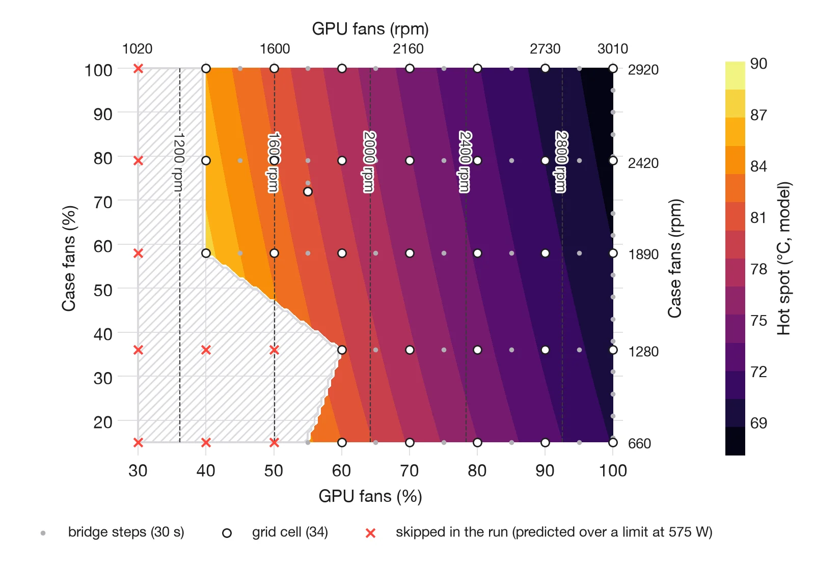
The load held 48.5 TFLOPS of FP32 arithmetic and 1.52 TB/s of memory traffic over 22 GiB, about 70 % of the card’s memory. Intake air stayed between 18.7 and 19.4 °C and drifted by −0.03 °C per hour; 341 sensors were logged once per second.
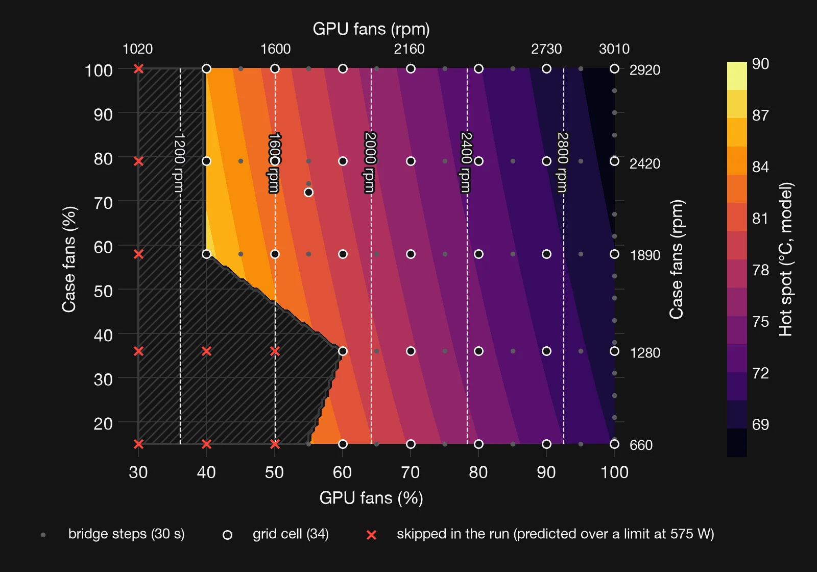
The grid cells lay at GPU fans of 40 to 100 % in steps of 10. Predicted to come within 5 °C of a limit, GPU fans at 30 % were skipped at every case speed. So were 40 and 50 % with the two slowest case speeds. The rule is conservative: in the power-limit run, GPU fans at 50 % with case fans at 15 % held 85.5 °C at 575 W.
The card’s own fans dominate
The fitted settled hot spot ranged from 68 °C, GPU fans at 100 %, to 90 °C with the GPU fans at 40 %. Turning the GPU fans down from 100 to 40 % raised it by 16 to 21 °C, depending on the case speed.
Two cells at 70 % GPU fans ran to full steady state. Turning the case fans down from 100 to 15 % raised the hot spot by 3.6 °C. With the top open, the card’s own fans change the hot spot several times as much as the case fans. This holds at medium and high GPU fan speeds. With the GPU fans at 40 %, the second run found a larger effect of the case fans: 9.0 °C on the core and 9.6 °C on the memory between 1000 and 2920 rpm.
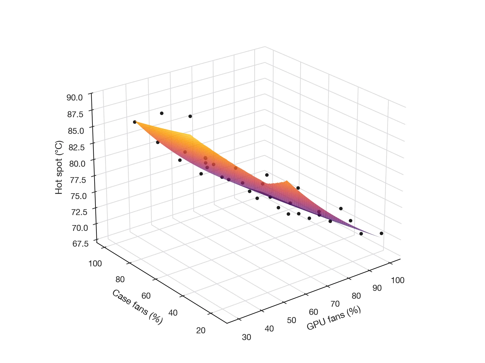
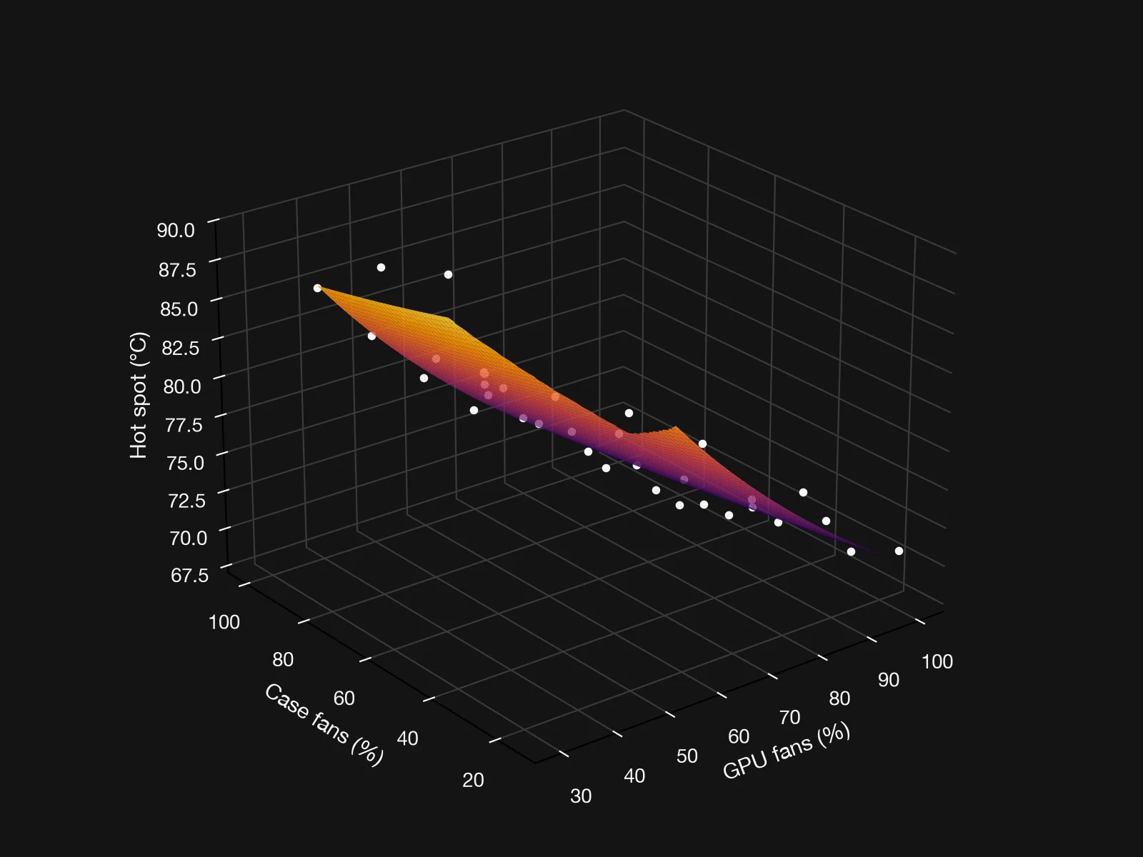
With the exponent fixed at 0.8, model (7) is linear in its coefficients. This first fit is ordinary least squares on , with fan speeds in rpm; the RMSE is on temperature. It uses 34 measurements: 31 grid cells and the reference cell three times.
| Sensor | , W/°C | of | RMSE, °C | |||
|---|---|---|---|---|---|---|
| hot spot | 4.26 | 0.0111 | 0.00195 | 5.7 | 0.966 | 1.1 |
| core* | 5.98 | 0.0126 | 0.00100 | 12.6 | 0.928 | 1.3 |
| memory* | 4.22 | 0.0127 | 0.00422 | 3.0 | 0.756 | 2.3 |
* Provisional. In 13 and 20 of the 34 cells the fit for the core and the memory failed, and the 60-second mean was used. Both rows will be refitted on steady-state cells.
The ratio is per rpm0.8. Over their measured ranges, the GPU fans change the conductance about 4 times as much as the case fans for the hot spot. For the core it is 9 times. For the memory the provisional fit gives twice, while the 60-second means give about 8 times (see ‘Core and memory’).
The interaction term is under 5 % of the GPU fan term for the hot spot and the core. For the memory it is about a quarter, with a negative sign.
is the intercept of a fit that starts at 1300 rpm, not a measured conductance without airflow. The nonlinear fit with residuals in °C, the free exponent and model (8) follow with the full analysis.
Core and memory
Core and memory are the primary limits; the hot spot is reported alongside them. Over the 34 grid cells the two move together, with a correlation of 0.988. The memory runs 6.4 to 9.4 °C above the core, 7.4 °C on average.
Each 1000 rpm more on the GPU fans lowered the core by 7.6 °C and the memory by 7.3 °C. Each 1000 rpm more on the case fans lowered them by 0.66 and 0.71 °C. These are 60-second means at 575 W with the top open; at low fan speeds such means read low, so the slopes are likely underestimates. One average slope also hides that the effect depends on the GPU fans: in the second run the case fans moved the core by about 9 °C with the GPU fans at 40 %, by about 3 °C at 60 % and by 2 °C or less from 70 % up.
With our 100 °C memory limit, the core had 0.6 to 3.6 °C less headroom than the memory in every cell, 2.6 °C on average, so the core binds first. Extending the fitted line, the memory would reach 100 °C only with the core near 92.6 °C. The highest memory reading so far was 81 °C, so this is a long extrapolation. All of this holds at 575 W; at lower power limits the gap widens and the memory can bind first (Memory temperature).
Clocks
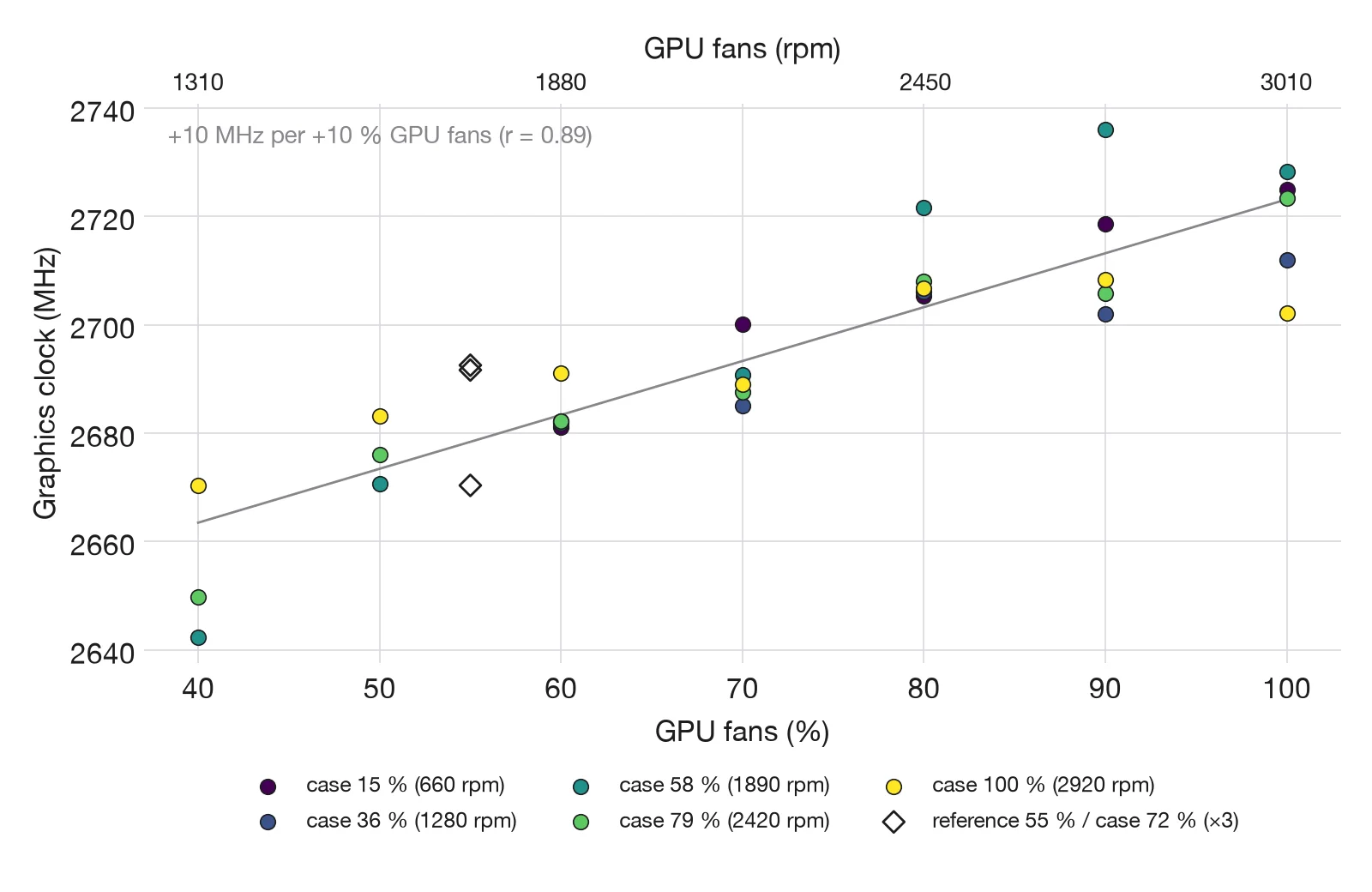
The memory clock read 14 001 MHz at every setting, so the memory never slowed down. The graphics clock ranged from 2642 to 2736 MHz over the 34 grid cells, 2695 MHz on average.
It fell slightly as the GPU fans slowed: from about 2700 to 2730 MHz at 100 % to about 2640 to 2670 MHz at 40 %, with a correlation of 0.89 to the fan setting. The card sat at its power limit in every second, so a hotter chip, which leaks more, gets less clock for the same 575 W: about 2 to 3 % less at the quietest settings. The reference cell varied by 22 MHz between its three repeats.
This is not thermal throttling: the core stayed below 75 °C, far from its 90 °C maximum, and the thermal throttle flags stayed clear in every cell.
Throughput did not follow the clock. It stayed between 48.4 and 48.7 TFLOPS, so a clock 2 to 3 % lower cost no measurable throughput with this load.
Is 60 seconds enough?
On the 30 grid cells with a well-defined fit, the median hot-spot time constant is 50 s. The middle half lies between 36 and 64 s. On all seven validation cells, the 60-second fit predicted the steady hot spot within 0.50 °C on average and 1.05 °C at most.
After a fan change the temperature closes the gap to its new settled value as . With s:
| Time after the change | Share of the change reached |
|---|---|
| 10 s | 18 % |
| 20 s | 33 % |
| 60 s | 70 % |
| 120 s | 91 % |
| 150 s | 95 % |
| 300 s | over 99 % |
A reading taken 10 to 20 seconds after a change therefore understates a step of 5 °C by 3 to 4 °C. In the pilot, full steady state took 150 to 350 seconds. Fitting equation (3) to 60 seconds of readings recovers the settled value without waiting that long.
The validation cells all had GPU fans at 55 or 70 %. The cells at 40 to 60 % have time constants up to 215 s and the largest extrapolation, and still need steady-state checks. Their 60-second means lie up to 5 °C below the fitted values.
Core and memory are reported in whole degrees, and a 60-second fit to a stepped signal is unreliable. Across the seven validation cells its error averaged 9.9 °C for the core and 8.6 °C for the memory. These two sensors need steady-state cells.
Repeatability
The reference cell sat at GPU fans 55 % and case fans 72 %. Its hot spot read 80.20, 80.48 and 80.46 °C at the start, middle and end of the run.
was 0.107 °C/W each time, and the core and memory read 70 and 78 °C all three times. Throughput stayed between 48.4 and 48.7 TFLOPS in every cell, so no measured setting cost speed at 575 W.
Between the two runs, the same setting at 575 W agreed within 1 °C with the case fans at 15 %, and differed by up to 4 °C at 100 %. Intake air and case fan speed matched; the cells differed in what came before them.
Fast 60-second cells reached from a warmer or a cooler state can differ by 3 to 4 °C. In the main run, where each step was small, the 60-second fits matched their settled values within 0.5 °C on average. The next run starts each power level with a settled cell.
Power limit
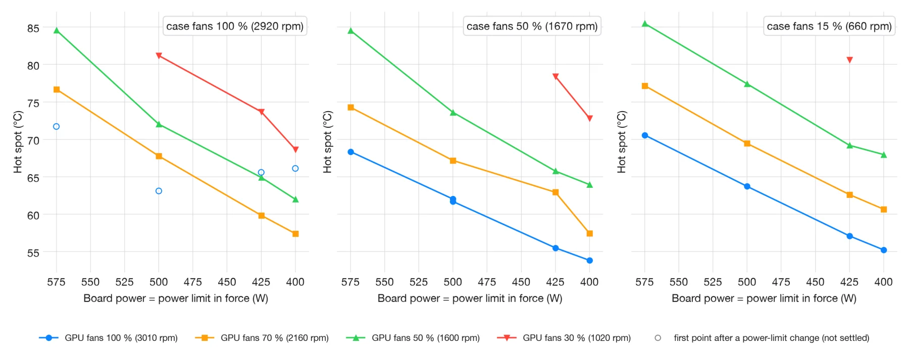
The power-limit run held the fans fixed and stepped the power limit down: 575, 500, 425 and 400 W. Of the 48 planned cells, 44 ran, and two of these stopped at a limit. The card accepts no limit below 400 W, 70 % of its stock limit.
At fixed fans, each 100 W less lowered the hot spot by about 8 to 13 °C. With case fans at 50 % and GPU fans at 70 %, it fell from 74.3 to 57.5 °C. In a quiet setting, case fans at 15 % and GPU fans at 50 %, it fell from 85.5 to 68.0 °C.
That slope is close to what equation (2) predicts: 100 W times an of about 0.1 °C/W.
The fan steps of this run were large, up to 30 points, so each fast cell may carry up to about 4 °C from the cell before. The slopes are approximate until the steady-state rerun.
GPU fans at 30 % were too hot at full power. They reached about 81 °C at 500 W with the case fans at 100 %, and 77 to 81 °C at 425 W with slower case fans. Except for one cell at 425 W, these cells had not fully settled after six minutes.
One of those slow cells, with a time constant of 125 s, settled: its 60-second fit was 1.3 °C high. In another, the last reading was already 1.2 °C above the fit.
With every fan at 100 %, the cell ran first after each change of power limit, straight after the hottest cell of the level before. The card was still cooling, so these values are shown as not settled and will be measured again. The cost in performance at each limit follows with the next data.
Second run: case fans, GPU fans and power limit
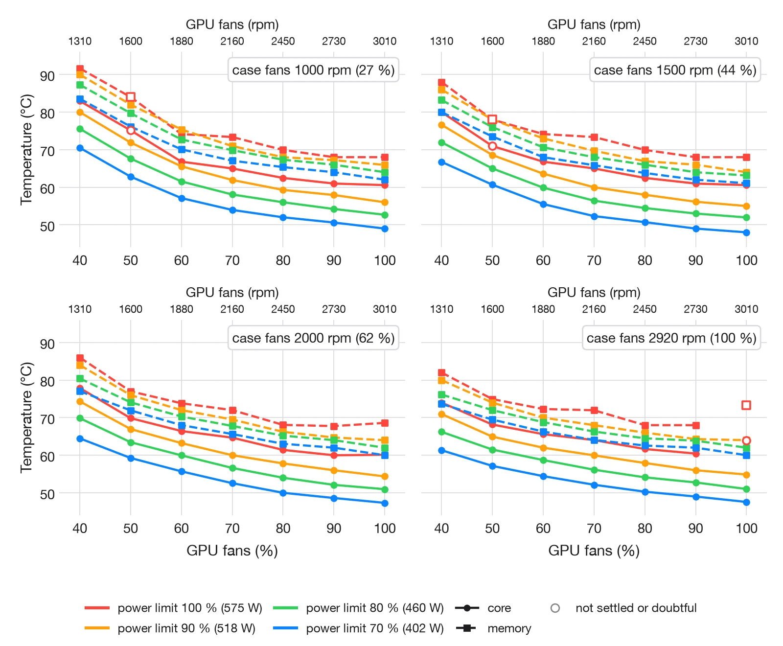
On 21 October we ran a second grid on the same GeForce RTX 5090 Founders Edition, with the top still open. The load was the same program with the same settings as in the first run; its throughput was not logged in the second run, so the 48.5 TFLOPS of the first run is not confirmed for it. Intake air stayed between 19.0 and 19.6 °C. This time the case fans were set in rpm: 1000, 1500, 2000 and 2920, their full speed, which is 27, 44, 62 and 100 % of the controller’s output. The GPU fans ran from 40 to 100 % in steps of 10, and at each setting the power limit was stepped through 100, 90, 80 and 70 %: 575, 518, 460 and 402 W. That is 112 points of 60 seconds each.
What the second run shows
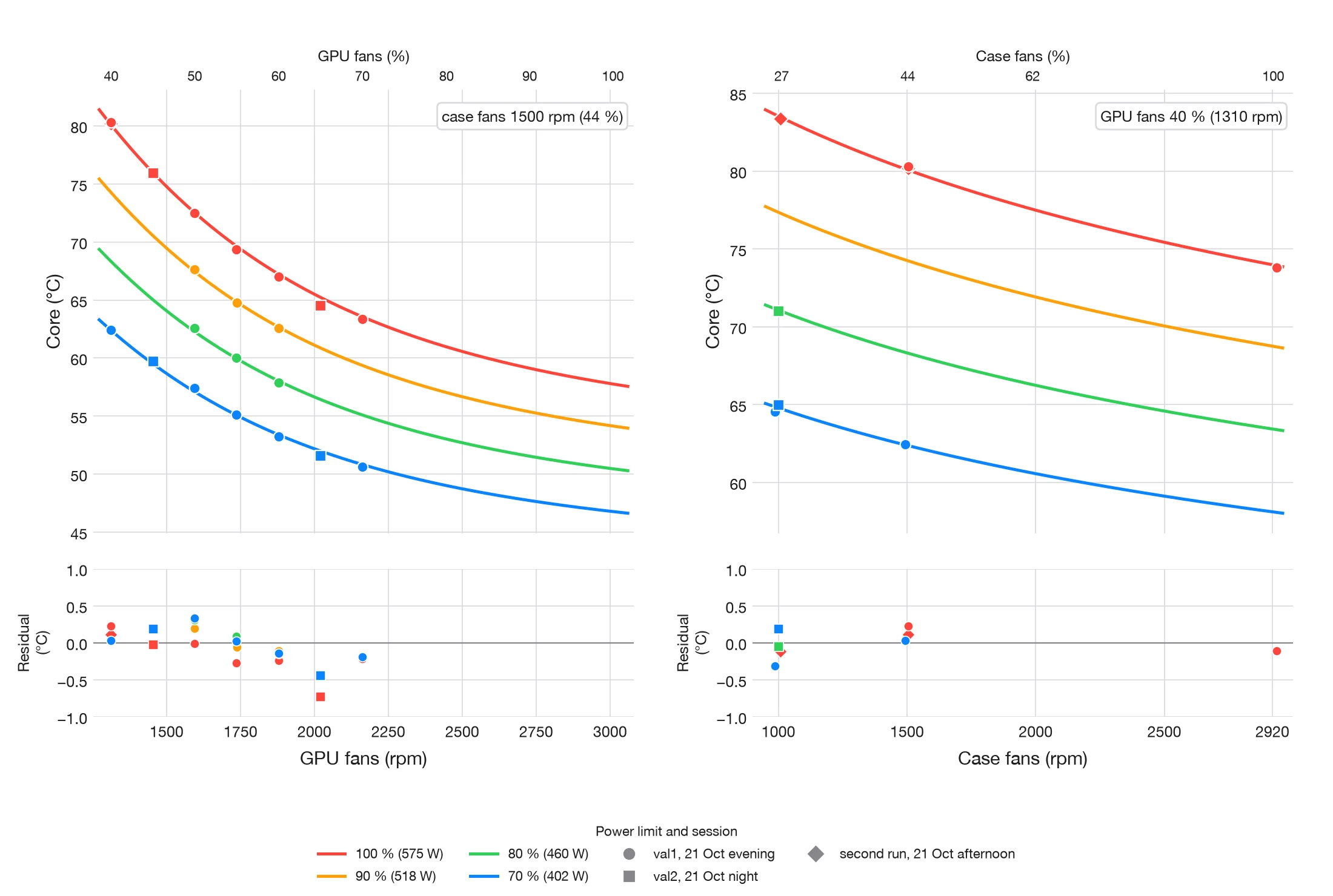
- The GPU fans dominate. At 575 W with the case fans at 1000 rpm, going from 40 to 100 % lowered the core from 83 to 61 °C and the memory from 92 to 68 °C, 22 and 24 °C; the values at 100 % are from the first run, at 1290 rpm. With same-day values at 518 to 402 W the fall was 14 to 24 °C on both, largest with slow case fans.
- The case fans matter mainly at low GPU fan speed. With the GPU fans at 40 %, case fans at 2920 instead of 1000 rpm lowered the core by 9.0 °C and the memory by 9.6 °C at 575 W, and by 9.0 to 9.4 °C and 9.9 to 11.2 °C at 518 to 402 W. At 60 % the core differed by 2.7 to 3.6 °C; from 70 % up by 2 °C or less, and the memory by up to 3.6 °C. These comparisons above 40 % use the 518 to 402 W rows only, all measured on the same day. This corrects the impression from the first run, whose average slopes mixed both regimes.
- The power limit cools the core more than the memory. From 575 to 402 W, with the GPU fans at 40 % where both ends are settled, the core fell by 12.5 to 13.4 °C and the memory by 8.0 to 9.0 °C. Over the whole table the falls range from 9.7 to 16.4 °C for the core and 4.0 to 13.3 °C for the memory, partly because the 575 W values above 50 % come from the first run. The gap between memory and core grew from 6.4 to 9.4 °C at 575 W to 11.9 to 13.5 °C at 402 W. The limit seems to act mainly on the core; we have not yet checked whether the memory keeps working at the same rate.
- The power limit costs clock. At 402 W the graphics clock was about 24 % lower: 2613 against 1975 MHz with the case fans at 1500 rpm and the GPU fans at 40 %.
- No thermal throttling. The card was held by its power limit at every point; the thermal throttle flags stayed clear. The hottest point, case fans 1000 rpm, GPU fans 40 % and 575 W, read 83 °C core, 92 °C memory and 94 °C hot spot: below the 90 °C core maximum and our 100 °C memory working limit.
| Case fans, rpm | 40 % | 50 % | 60 % | 70 % | 80 % | 90 % | 100 % |
|---|---|---|---|---|---|---|---|
| 1000 | 83/92 | 75/84* | 67/74n | 65/73n | 62/70n | 61/68n | 61/68n |
| 1500 | 80/88 | 71/78* | 67/74n | 65/73n | 62/70n | 61/68n | 61/68n |
| 2000 | 78/86 | 70/77n | 66/74n | 65/72n | 61/68n | 60/68n | 60/69n |
| 2920 | 74/82 | 68/75n | 66/72n | 64/72n | 62/68n | 60/68n | 64/73† |
| Case fans, rpm | 40 % | 50 % | 60 % | 70 % | 80 % | 90 % | 100 % |
|---|---|---|---|---|---|---|---|
| 1000 | 71/84 | 63/76 | 57/70 | 54/67 | 52/65 | 51/64 | 49/62 |
| 1500 | 67/80 | 61/74 | 56/68 | 52/66 | 51/64 | 49/62 | 48/61 |
| 2000 | 64/77 | 59/72 | 56/68 | 53/66 | 50/63 | 49/62 | 47/60 |
| 2920 | 61/74 | 57/69 | 54/66 | 52/64 | 50/63 | 49/62 | 48/60 |
Core / memory in °C, rows by case fan speed, columns by GPU fan speed. n Settled first-run value at the nearest case speed (about 1290, 1890 or 2920 rpm). * Not settled after 60 s, probably 2 to 3 °C low. † First-run point that sits above its neighbours; treat with caution.
How settled these points are
Sixty seconds per point is too short after a large step, as the section on settling predicts. Each 575 W point came straight after a 402 W point and was still warming at about 3 °C per minute, so it read 2 to 3 °C low. For 575 W the table and the figures therefore use the settled first-run values at the nearest case speed where they exist. The first run measured near 1290, 1890 and 2920 rpm, so the 1000 and 1500 rpm rows share its 1290 rpm values from 60 % GPU fans up. Two points at 50 % GPU fans had no first-run counterpart and are marked.
The first point of each case speed, GPU fans at 40 %, followed a step down from 100 % and read 10 to 15 °C low. We repeated those twelve points, letting each case speed settle for at least five minutes first; the figure and tables use the repeat. The 518, 460 and 402 W points were still falling at 2 to 3 °C per minute and may read 1 to 2 °C high. The next run lengthens each point after a large change of fans or power limit.
Data: final table (CSV) with a source column for every point, all 112 points as run (CSV) and the repeated 40 % points (CSV). The GPU fan rpm is the measured mean at each point.
How long a point needs
The evening validation series, val1, ran 20 points to steady state, each for about eight minutes, and logged the core 1, 2, 3, 5 and 8 minutes after the change. The settled value is the mean of the last 60 seconds. The table gives each snapshot minus the settled value.
| Time after the change | Small falling step (9 points) | Large step (10 points) |
|---|---|---|
| 1 min | +1.1 to +2.0 °C | −12.4 to +7.5 °C |
| 2 min | +0.2 to +1.0 °C | −6.7 to +4.2 °C |
| 3 min | 0 to +1.0 °C | −3.6 to +2.3 °C |
| 5 min | 0 to +0.7 °C | −1.0 to +0.6 °C |
Small falling step: power limit 10 points lower, fans unchanged. Large step: a change of case speed or GPU fans, or a power-limit step of 30 points. A negative value means the snapshot was still below the settled value, the card still warming. Every point (CSV).
Sixty seconds is therefore enough only after a small falling step, and even then reads 1 to 2 °C high. After a large step a point needs at least five minutes to come within 1 °C. The next runs use this rule.
One equation for the core
The core temperature of the second run follows one equation over all four case speeds, seven GPU fan speeds and four power limits:
is the GPU fan speed and the case fan speed, both in rpm, the board power in watts and the intake air, about 19 °C. The bracket is a thermal resistance; unlike in equation (1), it leaves out the offset . It falls as the GPU fans speed up, towards . The case fans scale only the part that depends on the GPU fans, so they matter when the GPU fans are slow and hardly at all when they are fast, as Figure 8 shows.
is a constant offset that does not grow with power. It may be heat that does not follow the power limit or an offset of the sensor; the dynamic model below points to warmer air at the card’s intake. It is an empirical term, not a physical constant.
For the second run, equation (9) replaces (7) and (8). It is written for the resistance rather than the conductance, contains the series resistance that (8) calls , adds the offset , and lets the case fans scale the fan term instead of adding to it. The exponent is empirical. Convection alone would give 0.5 to 0.8, as in A model of the cooler; the steeper fall suggests that at low speed the fans move less air through the fins than the fan laws predict. We compare forms on runs the model was not fitted to rather than by leave-one-out cross-validation: each 60-second point carries the history of the one before, so leaving one out does not test prediction. The first run’s fit of (7) stands as published.
We fit (9) to the 88 points of the final table measured on the same day: the 575 W values taken from the first run, at other case speeds, and the two unsettled points are left out. With 95 % bootstrap intervals over the points: = 10.0 °C (7.9 to 11.6), = 32.9 m°C/W (26.6 to 39.7), = 87.4 m°C/W (84.7 to 90.7), = 1.50 (1.25 to 1.75) and = 0.28 (0.20 to 0.36). The RMSE is 0.83 °C, = 0.990, and the largest residual 2.4 °C. Fitted to all 110 points of the final table instead, the RMSE is 1.14 °C and the largest residual 5.9 °C; fitted to the 110 raw 60-second readings, 0.82 °C.
and trade against each other: a larger offset with a smaller resistance fits almost as well, and the bootstrap pins their sum at 575 W, 25.5 to 31.5 °C, better than either alone.
The settled points of val1 show that this offset is mostly an artefact. At fixed fans, barely changes with the power limit: at 1500 rpm and 50 % GPU fans it is 91.9, 93.8, 94.4 and 94.6 m°C/W at 575, 518, 460 and 402 W, and at 60 % 82.9, 83.9, 84.0 and 83.8 m°C/W. So at steady state the rise is close to proportional to power; the small increase of at lower power corresponds to an offset of about 1 to 4 °C. Fitted to the 20 settled points alone, equation (9) gives = 2.5 °C with an RMSE of 0.54 °C, and 0.63 °C with no offset at all. The constants above, fitted to mostly 60-second points, read 1.9 °C high on these settled points on average and 2 to 4.8 °C high at 402 W: the 60-second readings at low power were still falling. The 10 °C offset of (9) is therefore largely an artefact of unsettled points; settled data put it at about 0 to 3 °C, in line with the dynamic model below. val1 points (CSV).
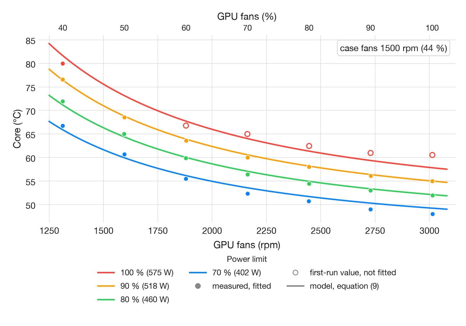
At 1500 rpm on the case fans alone, 22 points, the fit gives = 10.1 °C, = 30.0 m°C/W, = 90.5 m°C/W and = 1.46, with an RMSE of 0.66 °C and = 0.994. A log-linear form, , fits the same points with an RMSE of 1.33 °C, so we keep the resistance form. The resistance gives the core’s rise per 100 W at each GPU fan speed:
| GPU fans | rpm | °C per 100 W, (10) | °C per 100 W, (9) |
|---|---|---|---|
| 40 % | 1310 | 10.0 | 9.1 |
| 50 % | 1600 | 8.7 | 7.6 |
| 60 % | 1880 | 7.8 | 6.7 |
| 70 % | 2160 | 7.2 | 6.0 |
| 80 % | 2450 | 6.8 | 5.6 |
| 90 % | 2730 | 6.5 | 5.2 |
| 100 % | 3010 | 6.3 | 5.0 |
Case fans 1500 rpm. The dynamic model (10) gives about 1 to 1.3 °C more per 100 W than the static fit (9), because it keeps less of the rise in the offset ; the settled points of val1 support (10). Either way, lowering the power limit by 100 W cools the core about 1.6 to 1.8 times as much with the GPU fans at 40 % as at 100 %.
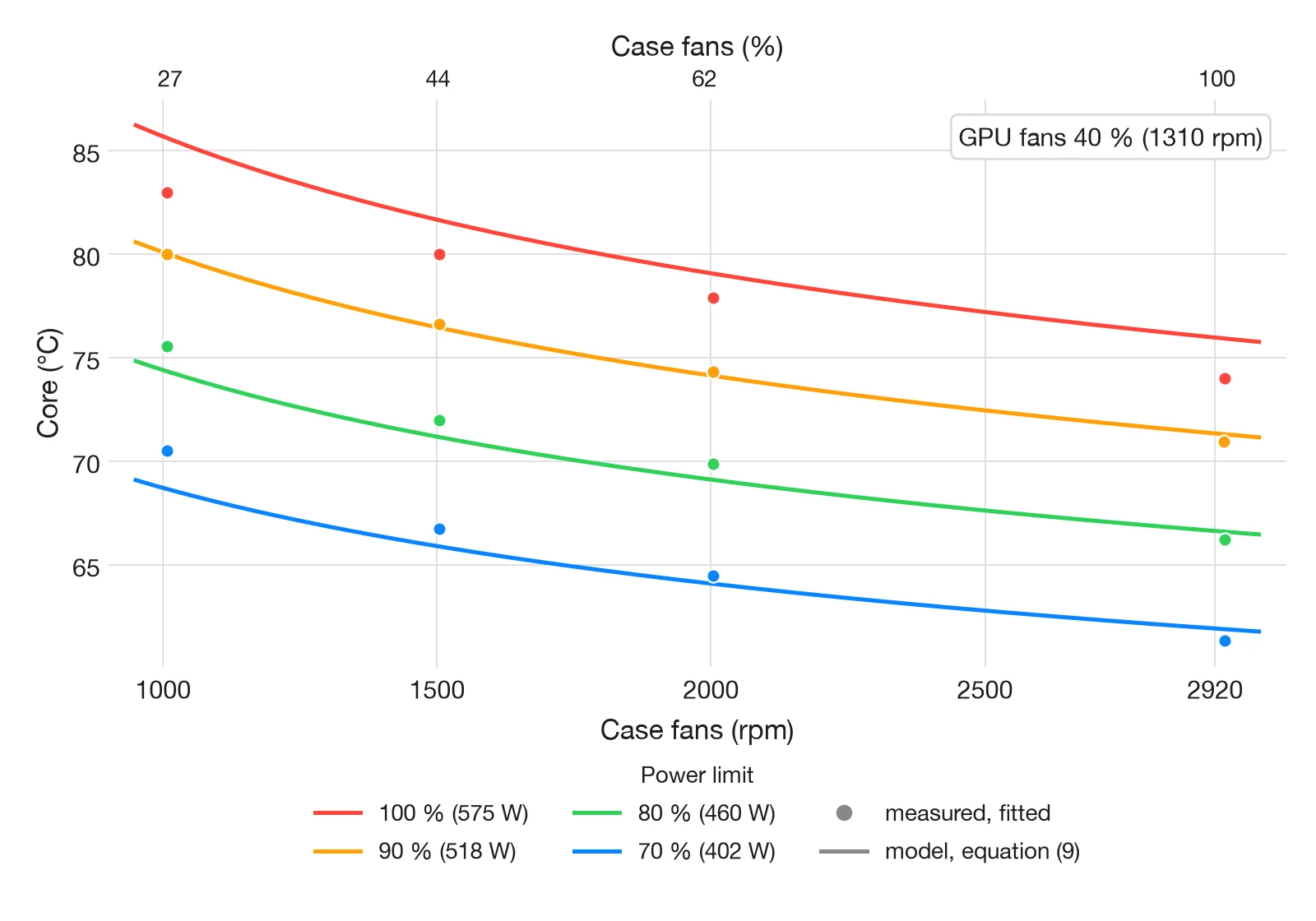
Most fitted points are 60-second readings, so the fit inherits their bias of 1 to 2 °C, described above. The equation describes one card with the top open and air at about 19 °C; another case or card needs its own constants.
A dynamic model from the 1 Hz logs
The static fit uses one value per point, and most of those values had not settled. A dynamic model avoids this: it is fitted to every second of the log, so a point that was still moving counts as moving. We simulate the core from the first sample of a run to the last, with the measured power, fan speeds and intake air as inputs and no resets, and fit the constants to the whole trajectory.
The best model has one thermal mass, the heatsink, and a resistance in series between it and the die:
is the heatsink temperature, the resistance from die to heatsink, the heatsink’s heat capacity and the part of the heatsink-to-air resistance that does not depend on the fans. We also fitted a heat capacity for the die; it came out close to zero, so the die follows the power within a second: at 575 W it sits about 22 °C above the heatsink. This is why a change of power limit acts at once, while a change of fan speed takes minutes. To keep the model finite when the GPU fans stop at idle, their speed enters as rpm.
Settled, the model gives , the same form as equation (9). Trained on the second run, with approximate 95 % intervals from the fit (the sample size reduced for the correlation between successive residuals): = 38.6 ± 0.5 m°C/W, = 11.4 ± 1.6 m°C/W, = 82.0 ± 0.6 m°C/W, = 1.67 ± 0.05, = 0.24 ± 0.01, = 3.2 ± 0.7 °C and = 1935 ± 53 J/°C. These intervals cover the scatter within the run, not the difference between sessions, which is larger (see below).
The same trade-off as in (9) appears here: and are correlated at −0.8. The static fit puts 10.0 °C in the offset with = 32.9 m°C/W; the dynamic one 3.2 °C with = 50.0 m°C/W. At 575 W the constant and fan-independent parts add up to 28.9 and 32.0 °C.
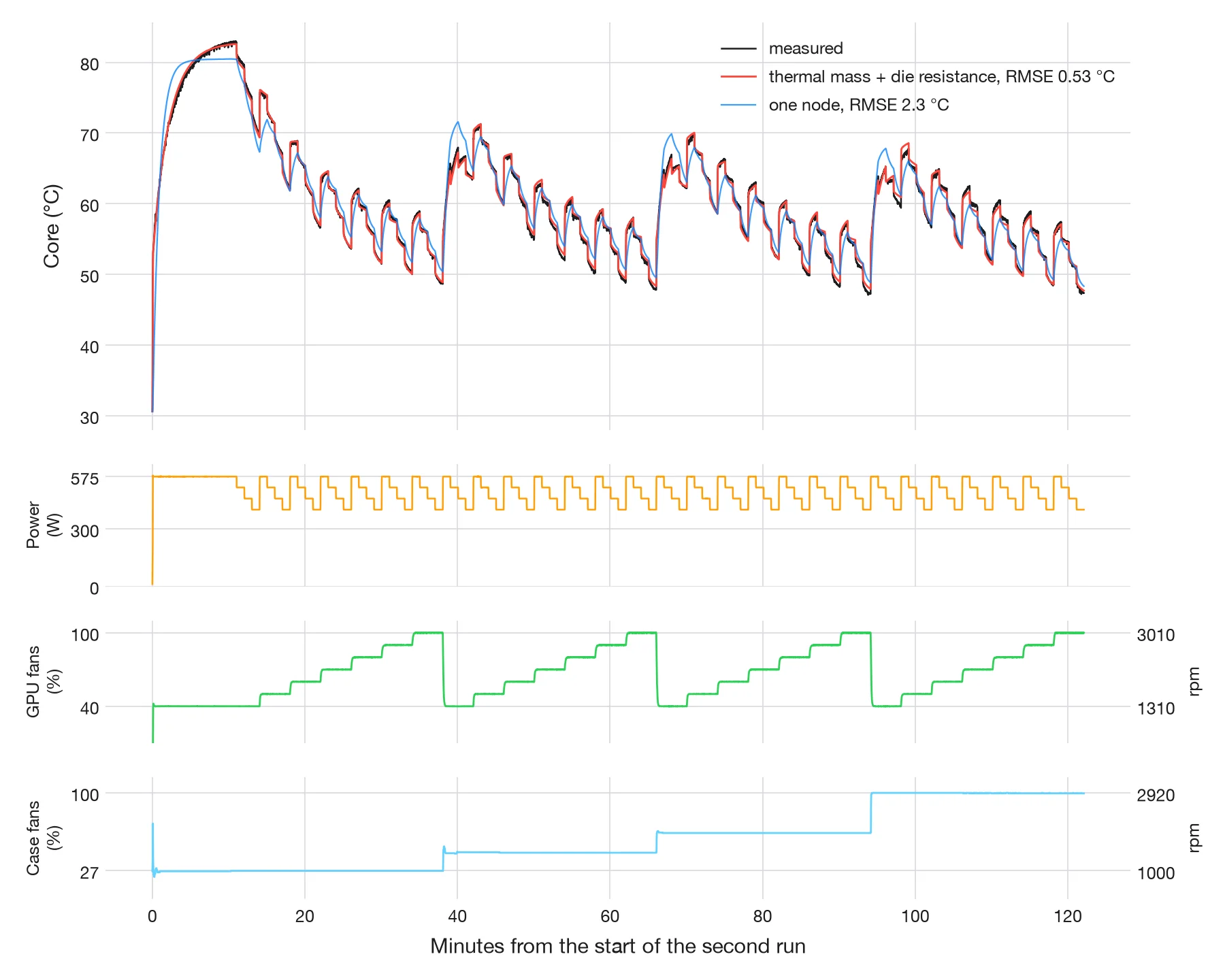
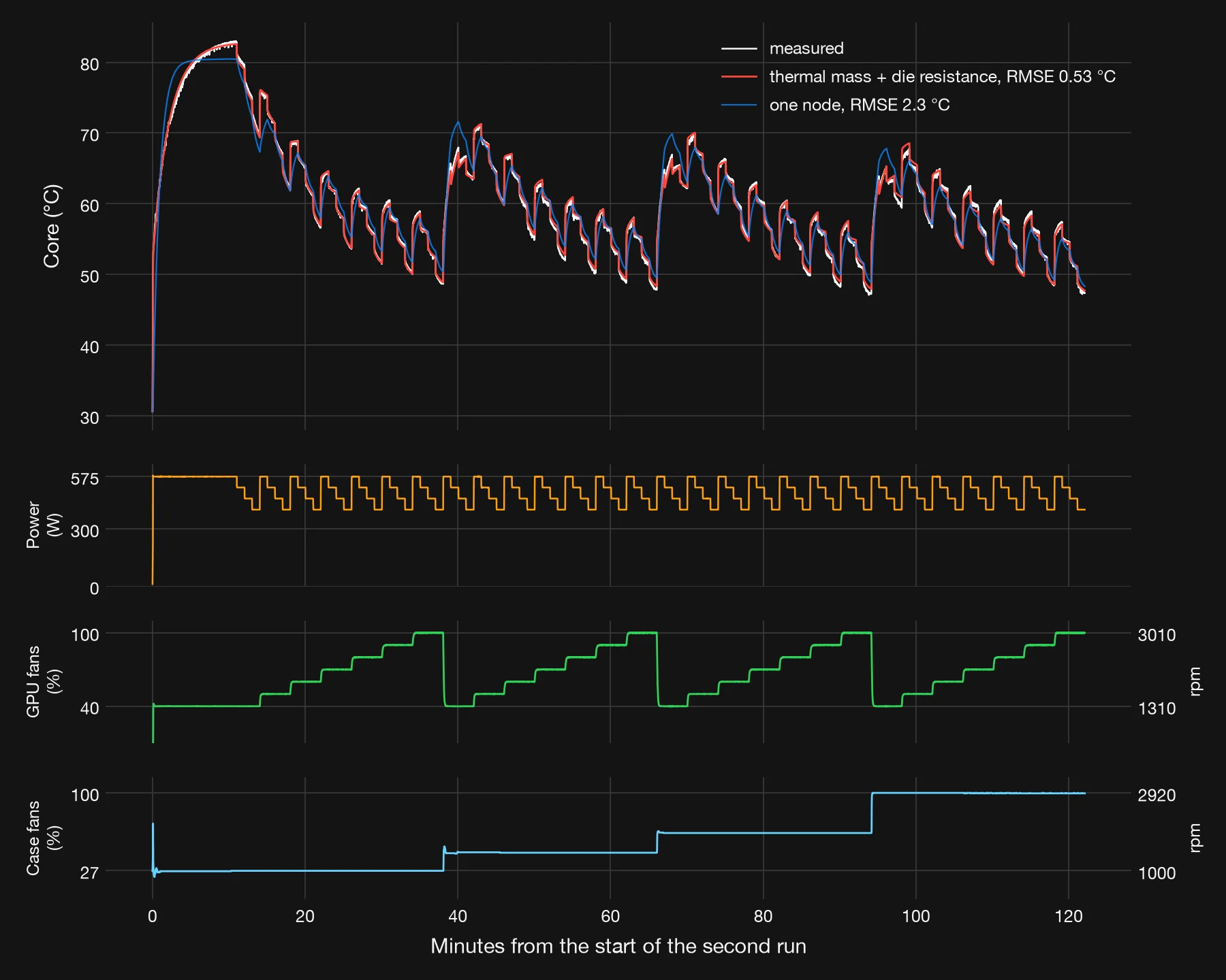
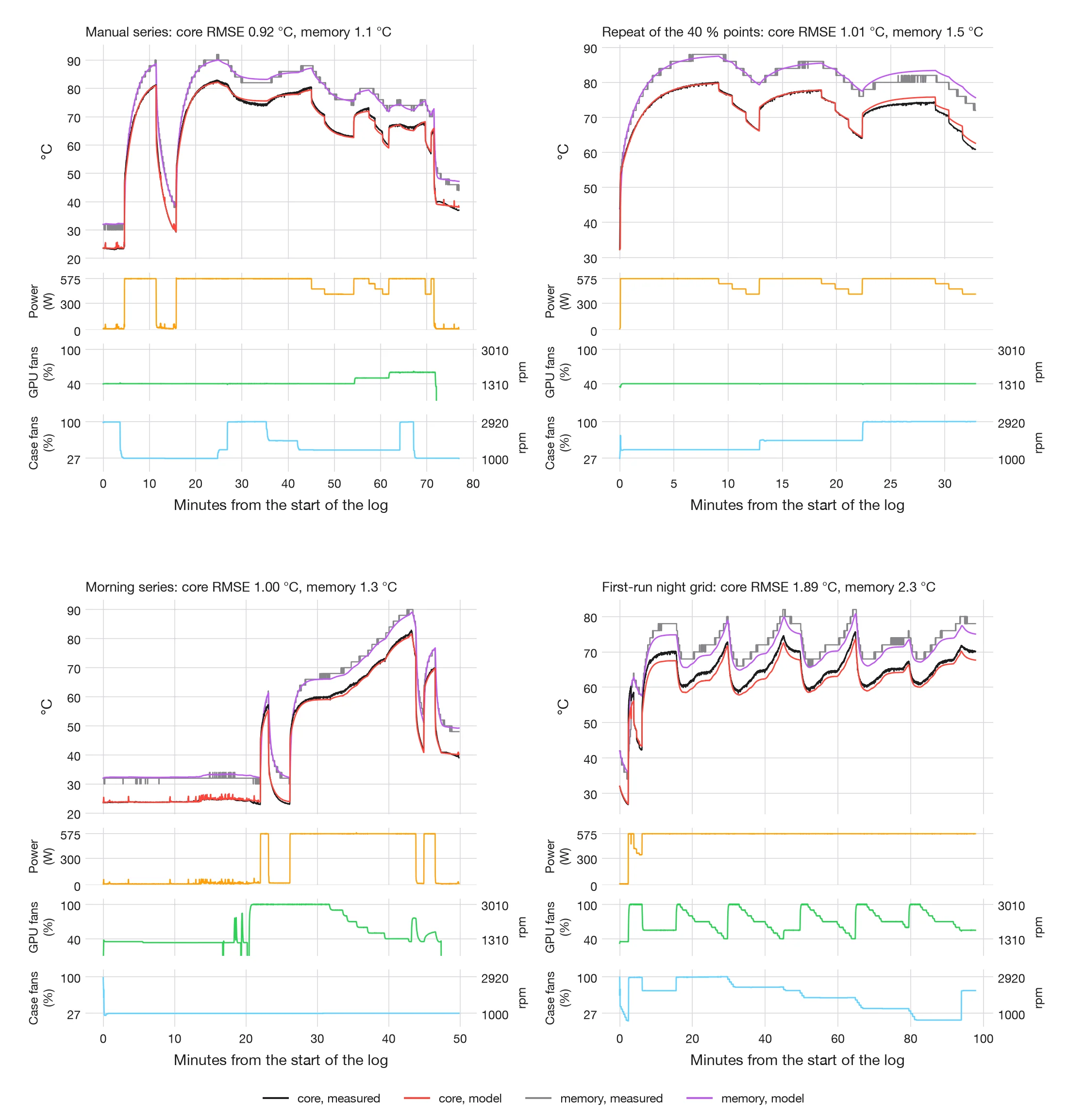
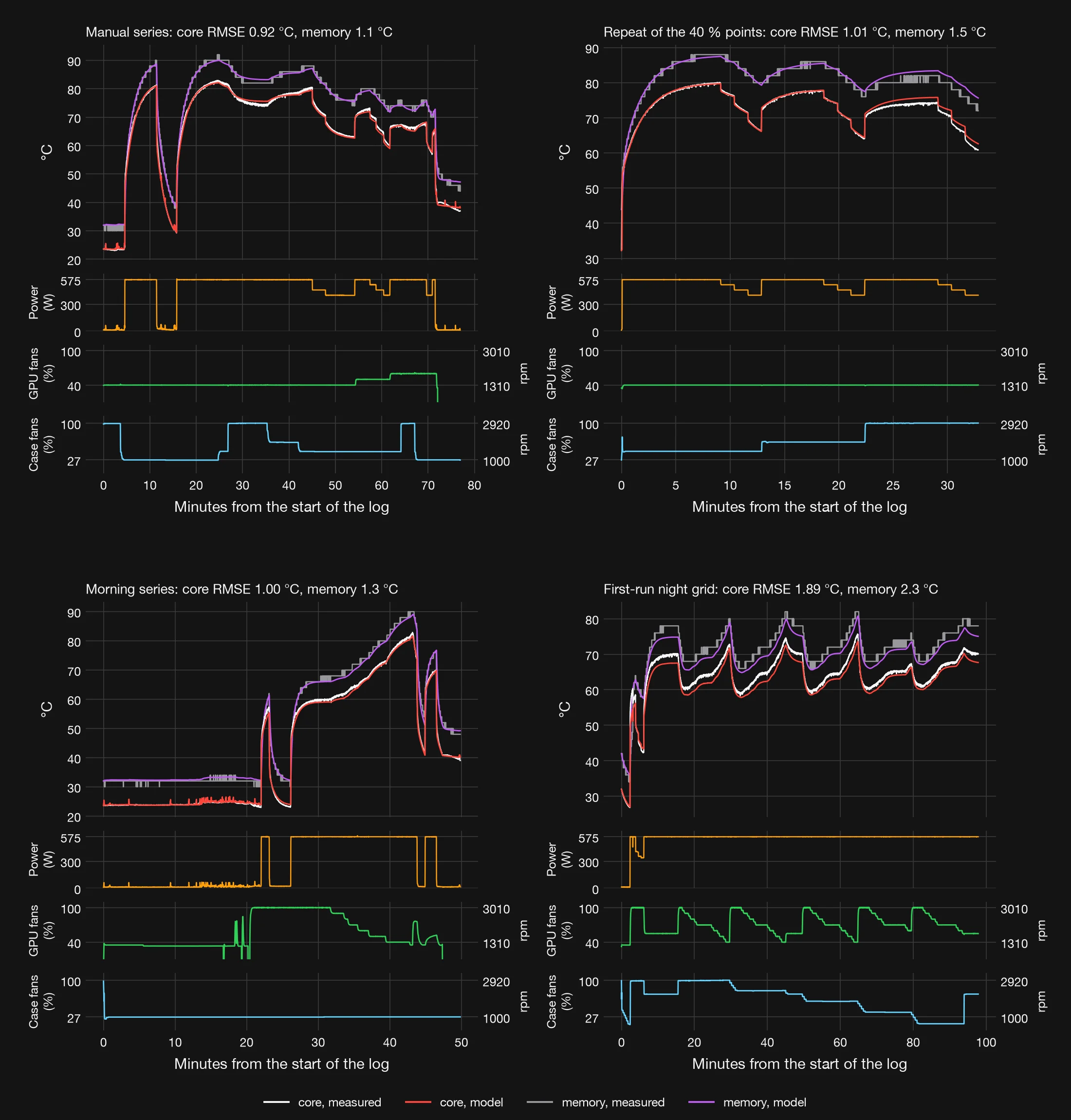
The simulated core matched the training run with an RMSE of 0.53 °C. On runs it was not fitted to, it did almost as well: 0.92 °C on the manual series, 1.01 °C on the repeat of the 40 % points, 1.00 °C on the morning series and 0.93 °C on the evening validation series val1, 0.95 °C pooled. On the 20 settled values of val1 its steady-state prediction has an RMSE of 0.67 °C and reads 0.4 °C high on average. In the repeat, once the case fans went to full speed after 22 minutes, the model ran about 1.5 °C high on the core and 3 °C high on the memory: it underrates the case fans at full speed when the GPU fans are slow. On the first-run night grid it reads about 2 °C low throughout, an RMSE of 1.89 °C.
A single node fails: 2.3 °C on the training run and 4.2 °C on the held-out daytime runs, because it cannot follow the fast jump of the die and the slow drift of the heatsink at once. A second heat capacity, between die and heatsink, adds nothing; it collapses to zero like the die’s. Forms that saturate at low airflow, or add a term for the heating of the air, did not predict the held-out runs better.
The heatsink’s time constant is its capacity times its resistance to the air, so it grows as the fans slow: 129 s with the GPU fans at 40 % and the case fans at 1000 rpm, 104 s at 40 % and 2920 rpm, and 43 to 50 s with the GPU fans at 100 %. This matches the 50 s median of the first run, where the GPU fans were mostly fast.
Two things change in the static picture. The residuals of equation (9) at low GPU fan speed and full power came from the unsettled points elsewhere in the fit, which distorted its constants: in the dynamic model the bias there is 0.2 °C. And shrinks from 10 to about 3 °C but does not vanish; forcing it to zero worsens the held-out daytime RMSE from 0.95 to 1.36 °C, and the settled val1 points independently give about 0 to 3 °C. Our best explanation is that the air reaching the card is warmer than the air at our sensor in the bottom chamber of the case, by an amount that varies from session to session; that would also explain the 2 °C offset of the night. The next runs add an air sensor at the card’s intake.
The memory follows the heatsink through one more node with a time constant of about 10 s. It is simulated with an RMSE of 0.9 to 2.3 °C, limited partly by its reading in whole degrees.
How the method was refined
A method is only as good as the evidence that corrects it. Ours changed several times in two days, and each change was forced by something the data showed. What follows is that sequence: what we measured and for how long, what the residuals and the statistics revealed, and what we changed in response.
20 to 21 October: a fast grid
On the evening of 20 October a 41-minute pilot ran a four-by-four grid to steady state. Its points took 150 to 350 seconds to settle, too long for a full grid in one night. The night grid of 34 cells therefore gave each cell 70 seconds: 10 discarded, 60 logged, and a first-order fit to extrapolate the settled value. The grid took 98 minutes and the power-limit run another 3.25 hours.
The fit worked for the hot spot, within 0.5 °C on the validation cells. For the core and the memory it failed in 13 and 20 of the 34 cells: these sensors reported whole degrees, and an exponential cannot be fitted to a staircase. Cells reached from a warmer or a cooler state also disagreed by 3 to 4 °C. We kept the hot-spot results and planned settled cells for the core.
21 October, morning: looking by hand
A 50-minute morning series held the case fans at 1000 rpm and stepped the GPU fans by hand; a 77-minute manual series then varied both sets of fans and the power limit. Two facts appeared that the grid had hidden. With slow GPU fans the case fans move the core by about 9 °C, not by the 0.66 °C per 1000 rpm that the averaged slopes of the first run suggested. And the power limit acts at once and strongly; the card accepts no limit below 400 W.
21 October, afternoon: a bigger grid and its bias
The second run measured 112 points of 60 seconds in 122 minutes, over case fans, GPU fans and power limit. The residuals of the static model (9) were not random. They were largest where a point followed a large step: the 575 W points, each after a 402 W point, read 2 to 3 °C low, and the 40 % points at the start of each case speed read 10 to 15 °C low. The fitted offset came out at 10 °C, with a bootstrap interval of 7.9 to 11.6 °C, too large to be a physical constant. A 33-minute repeat ran the twelve worst points to steady state, and from then on we stopped trusting single short readings.
Fitting the whole time series
Instead of one number per point, we fitted a dynamic model to every second of the logs, equation (10). Its time constants explained the bias quantitatively: is 43 s with fast GPU fans and up to 129 s with slow ones, and after a step the remaining error decays as . Sixty seconds is less than half of at low fan speed, so a short reading there misses most of the change. Tested on runs it had not seen, the model predicted the core within about 1 °C.
21 to 22 October, evening and night: validation
Three series tested these conclusions directly. Val1, 168 minutes from 17:54, ran 20 points to steady state and logged the core 1 to 8 minutes after each change. It showed how long a point needs: 60 seconds after a small falling step, five minutes after a large one. It also showed that at steady state the rise is close to proportional to power, so the 10 °C offset was an artefact of unsettled points.
Dyn1, 159 minutes from 20:42, applied 56 random steps of 60 to 240 seconds over the full range of fans and power, chosen by Latin-hypercube sampling, with a ten-minute anchor every twentieth step. Steps that do not repeat a pattern identify a dynamic model better than a regular grid. The model trained on the afternoon grid predicted dyn1 with an RMSE of 0.56 °C; leaving each run out of the training in turn, the pooled error was 0.72 °C. Val2, 72 minutes from 23:21, added nine settled points at GPU fan speeds of 45 and 65 %, which no model had seen.
22 October: statistics on settled points
With the settled points of four sessions we tested the steady-state model formally, in the next section. Three more corrections came from that analysis. First, the settling check had used whole-degree readings, so with the GPU fans at 40 to 45 % it declared points settled while the core was still rising by 0.2 to 0.4 °C, with of 115 to 155 s; the core is now read from the NVAPI sensor at 0.01 °C, and every point is extrapolated to its final value. Second, the sessions differ by up to 2.4 °C, more than any two model forms; each session now has its own offset, and repeated anchor points measure drift directly. Third, the residuals still run along the fan axis, and the tests trace this to the shape of the curve, not to sensor rounding or drift. The steady2 series of 22 October, a dense grid in a single session with anchors, is filling the empty cells of the design.
Each correction made a point slower to measure and the method more honest. The rule we keep is simple: a reading taken before the card has settled is not a measurement of the settled state, so either each point waits until it has settled, or the model is fitted to the whole time series.
Statistical tests
This section tests the steady-state model on settled points only. The data are 38 points, each run until the core stopped moving and then extrapolated to its final value: val1 (21 October, evening): 20; val2 (21 to 22 October, night): 9; first-run night grid (20 to 21 October): 7; second run, afternoon (21 October): 2. The core is read from the NVAPI sensor at 0.01 °C, and each point’s final value comes from fitting to its last minutes. Units are °C throughout, thermal resistance in m°C/W and conductance in W/°C.
The model
is an offset for each measuring session , zero for the reference session val1. The heatsink passes heat to the air along two paths in parallel, one driven by the card’s fans and one by the case airflow; their conductances add. That is why the case fans matter when the GPU fans are slow and hardly at all when they are fast. is the resistance that no airflow removes. The constants are estimated by nonlinear least squares (Levenberg–Marquardt).
Equation (11) replaces the static fit (9) for settled points. Its exponent = 2.45 is far above the 0.5 to 0.8 that convection alone would give (section A model of the cooler): here the conductance also carries the fan’s own airflow curve, so is an empirical constant. The case-fan path is the least certain constant; its interval includes zero, because the settled points so far cover few case speeds.
| Constant | Estimate | SE | SE HC3 | SE cluster, session | SE cluster, series | 95 % interval, HC3 |
|---|---|---|---|---|---|---|
| 1.93 °C | 0.59 | 0.54 | 0.14 | 0.54 | 0.87 to 2.98 | |
| 53.95 m°C/W | 3.08 | 6.04 | 5.51 | 5.60 | 42.11 to 65.78 | |
| 6.44 W/°C | 1.65 | 2.89 | 2.30 | 2.24 | 0.78 to 12.11 | |
| 2.45 | 0.43 | 0.89 | 0.78 | 0.73 | 0.71 to 4.20 | |
| 8.10 W/°C | 2.79 | 5.08 | 4.14 | 4.08 | −1.86 to 18.06 | |
| 0.81 | 0.19 | 0.30 | 0.21 | 0.23 | 0.22 to 1.41 | |
| , second run, afternoon (21 October) − val1 | 0.08 °C | 0.42 | 0.37 | 0.11 | 0.14 | −0.64 to 0.80 |
| , first-run night grid (20 to 21 October) − val1 | 2.43 °C | 0.22 | 0.43 | 0.09 | 0.41 | 1.58 to 3.27 |
| , val2 (21 to 22 October, night) − val1 | 0.11 °C | 0.18 | 0.25 | 0.10 | 0.16 | −0.37 to 0.60 |
The fit has an RMSE of 0.37 °C. Refitted with each point left out in turn, it predicts that point with an RMSE of 0.52 °C (leave-one-out); five-fold cross-validation gives 0.55 °C. Because the Breusch–Pagan and White tests reject constant variance, we report heteroscedasticity-consistent (HC3) standard errors. Cluster-robust errors by session rest on only 4 clusters and are indicative only.
Forms and transforms we tried
We fitted nine forms of the resistance, each with and without session offsets, and compared them by leave-one-out and five-fold cross-validation, by leaving out whole sessions, and by the Bayesian information criterion (BIC). Without session offsets every simple form leaves an RMSE of 0.82 to 0.96 °C; the sessions differ by more than the forms do. With offsets:
| Form of R(N, C), with session offsets | Constants | RMSE | Leave-one-out | 5-fold | Leave session out | BIC | DW along N |
|---|---|---|---|---|---|---|---|
| power, k N−m C−q | 9 | 0.56 | 0.84 | 0.88 | 1.44 | 97.1 | 0.45 |
| exponential in N | 9 | 0.43 | 0.63 | 0.65 | 1.33 | 77.2 | 0.39 |
| rational in N | 9 | 0.53 | 0.79 | 0.82 | 1.42 | 91.9 | 0.47 |
| two parallel conductances (chosen) | 10 | 0.37 | 0.52 | 0.55 | 1.35 | 68.2 | 0.42 |
| effective airflow, k (N + bC)−m | 9 | 0.43 | 0.56 | 0.61 | 1.35 | 76.1 | 0.39 |
| per-watt response, same form | 10 | 0.37 | 0.51 | 0.54 | 1.31 | 64.1 | 0.41 |
| log-log with interactions | 11 | 0.34 | 0.71 | 0.73 | 1.46 | 64.4 | 0.57 |
| natural cubic spline in ln N | 12 | 0.39 | 0.80 | 0.92 | 1.34 | 79.3 | 0.56 |
| tensor spline surface (benchmark) | 17 | 0.13 | 8.04 | 26.29 | 81.69 | 11.9 | 1.38 |
RMSE and cross-validation errors in °C. BIC on the scale of , with the Jacobian term for transformed responses.
The tensor spline fits the points almost exactly but predicts new ones badly (leave-one-out 8.0 °C): the design still has empty cells, so it serves as a benchmark, not a model. Among the parametric forms, two conductances in parallel predict best. We also tried transforming the response. The Box–Cox profile, transforming both sides, gives = 1.65 with a 95 % interval from −0.95 to 3.00, which includes 1, no transform. Modelling the per-watt rise instead is the same mean with weights proportional to and gives nearly the same constants. A log-log regression gives elasticities at the mean of 0.95 for power, −0.59 for the GPU fans and −0.08 for the case fans: the rise is almost proportional to power. A power curvature gives = 0.90 and only a small gain (RMSE 0.36 °C).
A first-difference estimator along the GPU fans, within each series of fixed session, case speed and power limit, removes and the session offsets altogether. On 15 pairs it gives = 5.7 ± 0.3 W/°C and = 2.44 ± 0.09, in line with the fit on levels.
The tests
| Test | Statistic | p | Verdict on the null |
|---|---|---|---|
| Mean residual is zero | 0.000 °C | 1.00 | not rejected |
| Durbin–Watson along the GPU fans, within each series | 0.42 | < 0.001 | rejected |
| Durbin–Watson in time order | 2.49 | 0.82 | not rejected |
| Breusch–Godfrey, order 1, along the GPU fans | 8.51 | 0.004 | rejected |
| Breusch–Godfrey, order 2, along the GPU fans | 8.52 | 0.01 | rejected |
| Breusch–Godfrey, order 1, in time | 3.13 | 0.08 | not rejected |
| Breusch–Godfrey, order 2, in time | 3.42 | 0.18 | not rejected |
| Correlation of residuals with GPU fan speed | r = −0.02 | 0.89 | not rejected |
| … with case fan speed | r = 0.08 | 0.64 | not rejected |
| … with power | r = 0.00 | 1.00 | not rejected |
| … with intake air | r = 0.08 | 0.65 | not rejected |
| … with time | r = 0.00 | 0.98 | not rejected |
| Breusch–Pagan (Koenker), constant variance | 13.70 | 0.003 | rejected |
| White, constant variance | 31.95 | < 0.001 | rejected |
| White, special form | 1.37 | 0.50 | not rejected |
| Shapiro–Wilk, normal residuals | W = 0.908 | 0.004 | rejected |
| Jarque–Bera, normal residuals | 19.88 | < 0.001 | rejected |
| Shapiro–Wilk without the outlier | W = 0.956 | 0.15 | not rejected |
| Jarque–Bera without the outlier | 1.36 | 0.51 | not rejected |
| Ramsey RESET, squared fitted values | 0.80 | 0.38 | not rejected |
| Ramsey RESET, squares and cubes | 1.60 | 0.22 | not rejected |
| Lack of fit against pure error from replicates | 11.11 | 0.003 | rejected |
| Session offsets are zero (Wald, HC3) | 33.17 | < 0.001 | rejected |
| Box–Cox, no transform needed (λ = 1) | λ̂ = 1.65 | 0.59 | not rejected |
| No drift within a session (repeated anchor points) | +0.015 °C/h | 0.51 | not rejected |
Durbin–Watson p-values are exact, by Monte Carlo under the null given the regressors. The outlier is a first-run night-grid point at GPU fans 70 %, case fans 654 rpm and power limit 100 %, with a studentised residual of +5.5.
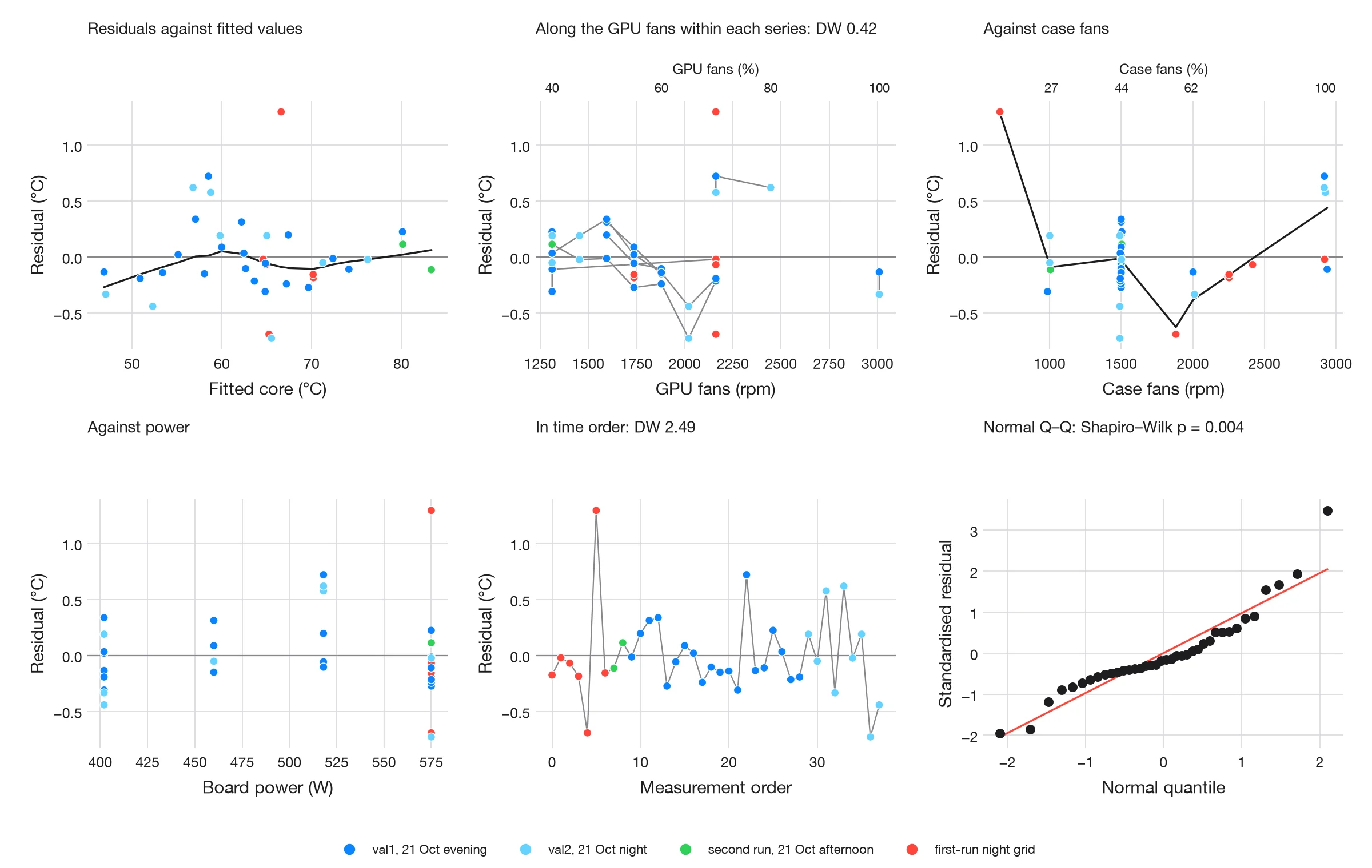
The residuals average zero and do not correlate with any input, with the fitted value or with time. In time order they show no autocorrelation (Durbin–Watson 2.49), and the repeated anchor points drift by +0.015 °C per hour, indistinguishable from zero. Their variance is not constant, hence the HC3 errors, and their distribution is normal once the one outlier from the night grid is set aside. The session offsets are real: = 33.2, p < 0.001.
An open item: the residuals run along the GPU fans
Within each series the residuals change sign slowly as the GPU fans speed up: Durbin–Watson along the fan axis is 0.42, p < 0.001, and the lack-of-fit test against the pure error of repeated points (standard deviation 0.14 °C) rejects the form, p 0.003. We tested three causes.
- Sensor rounding is not the cause. Durbin–Watson is 0.51 with the whole-degree NVML readings, 0.40 with NVAPI at 0.01 °C and 0.42 after the settling correction.
- Drift is not the cause. In time order Durbin–Watson is 2.49, the Breusch–Godfrey test in time is not significant, and the anchors drift by 0.015 °C per hour.
- The shape of the curve is the cause. A tensor-spline surface with a term and session offsets brings Durbin–Watson to 2.00 (p = 0.50) and the RMSE to 0.11 °C, close to the pure error.
| Variant | RMSE, °C | DW along N |
|---|---|---|
| Core read in whole degrees (NVML) | 0.37 | 0.51 |
| Core at 0.01 °C (NVAPI), mean of the last 60 s | 0.37 | 0.40 |
| Core at 0.01 °C, extrapolated to the settled value (used) | 0.37 | 0.42 |
| Chosen form with power curvature Pβ, β = 0.90 | 0.36 | 0.53 |
| Chosen form without session offsets | 0.85 | 0.09 |
| Spline in ln N, with session offsets | 0.39 | 0.56 |
| Tensor spline, with session offsets | 0.13 | 1.37 |
| Tensor spline R(N, C) with a P2 term and session offsets | 0.11 | 2.00 |
| Chosen model, repeated points averaged | 0.37 | 0.42 |
What remains, a few tenths of a degree, is a smooth error in the shape of the fan-response surface, with a slight concavity in power. We do not “correct” it with generalised least squares, because it is a symptom of the form, not of the noise; a Prais–Winsten fit with = 0.66 moves the constants within their standard errors. The flexible surface cannot yet be estimated reliably, because the design still has empty cells. The steady2 series of 22 October, a dense grid of case speed by power limit in one session with repeated anchor points, is filling them.
Sessions
A mixed model with a random intercept per session (REML, shape constants held at their least-squares values) puts the spread between sessions at 1.17 °C and the residual spread at 0.40 °C; the intra-class correlation is 0.90. The night session sits 1.7 °C from the average session, while the daytime sessions lie close together. Predicting a session the model has never seen costs about 1.3 °C RMSE. The state of the case on the day, most likely the temperature of the air reaching the card, matters more than any remaining error of shape.
Data: settled points (CSV), residuals (CSV), model comparison (CSV) and all results (JSON). Scripts: steady_data.py, steady_stats.py, fig_steady.py in the public data repository.
From model to controller
The models exist to drive a controller. WS.Sensor, part of WS.Remote, will run it once a second on the workstation itself. Its design follows from what we measured, and we tested it in simulation against the factory fan curve before letting it near a real machine. It is not yet deployed.
How it decides
- Feed-forward from the model. Every five seconds, and at once when the load steps, the controller searches the GPU and case fan speeds for the quietest pair whose predicted settled core, from equation (11), stays below the target minus a margin, and whose memory stays below 96 °C, our 100 °C working limit less 4 °C. The margin is twice the model’s leave-one-out error, at present 1.0 °C.
- Feedback for what the model misses. A proportional-integral term on the core error, tuned in simulation on the dynamic model (10), corrects the feed-forward. The proportional part only raises the fans; the integral trims both ways within 3 °C of the target and stops at the limits, so it cannot wind up while the card idles.
- Fans first, power last. Only when the mode’s noise ceiling is reached does the controller lower the power limit, by at most 5 % every 30 seconds and never below what the model and its margin require; it raises the limit again as soon as the core is 1.5 °C below the target. Performance mode never lowers it.
- Slow to calm down. The fans speed up by up to 150 rpm per second but slow down by only 15 rpm per second, and only after 60 seconds below the target less 1.5 °C. The load estimate rises at once and is held for five minutes, so short pauses do not set the fans hunting. The GPU fans never stop under load: their floor is 30 % at idle and 40 % at full load.
| Mode | Core target | GPU fan ceiling | Case fan ceiling | May lower the power limit |
|---|---|---|---|---|
| Quiet | 80 °C | 1800 rpm (57 %) | 1200 rpm | yes |
| Balanced | 77 °C | 2300 rpm (75 %) | 1500 rpm | yes |
| Performance | 72 °C | 100 % | full speed | no |
What the simulation shows
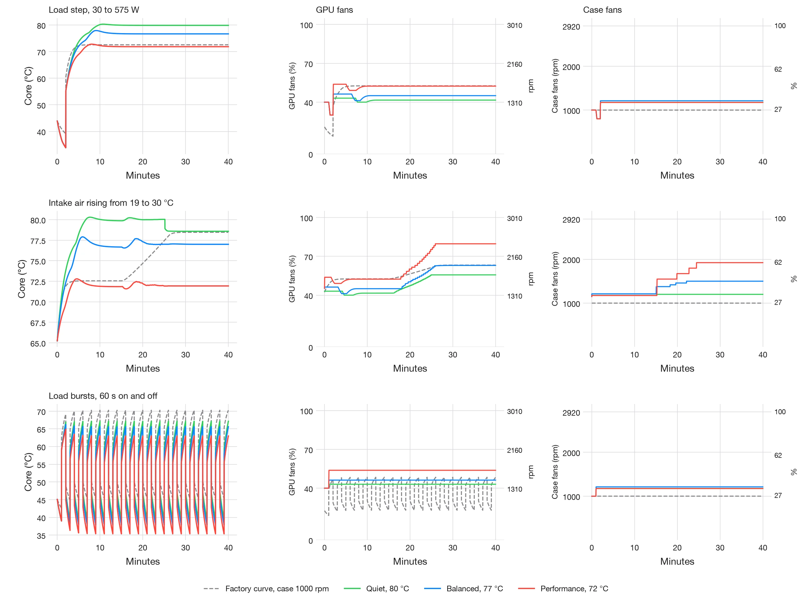
The simulated card is the dynamic model (10) with its memory node. The factory curve is modelled from the card’s driver fan curve with the case fans fixed at 1000 rpm. Three scenarios: a load step from 30 to 575 W, intake air rising from 19 to 30 °C at full load, and load bursts of 60 seconds on and off.
| Controller | Load step: peak core, °C | Warm intake: peak core, °C | Warm intake: seconds above target + 1 °C | Bursts: fan reversals per minute | Load step: noise proxy |
|---|---|---|---|---|---|
| Factory curve | 72.5 | 78.5 | 842 | 0.97 | 48.3 |
| Quiet, 80 °C | 80.3 | 80.3 | 0 | 0.00 | 45.1 |
| Balanced, 77 °C | 77.9 | 77.9 | 0 | 0.00 | 46.4 |
| Performance, 72 °C | 72.8 | 72.8 | 0 | 0.00 | 48.9 |
For the factory curve the warm-intake column counts seconds above 78 °C, the Balanced target plus 1 °C. The noise proxy is computed from fan speed, 50 log10 of the speed ratio for each fan group summed on an energy basis; it ranks settings but is not a sound level in decibels.
After the load step every mode settles at its target without overshooting it by more than 1 °C. When the intake air warms by 11 °C, the factory curve lets the core drift up to 78.5 °C and stays above 78 °C for 842 seconds, while each of our modes holds its target, with no second more than 1 °C above it. Under load bursts the factory curve reverses the direction of its fans 0.97 times a minute, the audible pumping of a fan that chases every burst; ours never reverses. The price is that our fans stay at the loaded speed between bursts, a steadier but slightly higher level of noise.
The simulation also exposed a fault, and the fault taught us something. In the first version, in Quiet mode with warm intake air, the controller cut the power limit to 70 % for about five minutes, cooling the core to 67 °C, before settling at 95 %. The cause was the load estimate: it divided the held peak of power by the current power limit, so every step down of the limit raised the estimated demand, which called for a further step down. The corrected controller, in WS.Sensor 0.30.55, divides the measured power by the limit only when the card is actually held at its limit, lowers the limit by at most 5 % every 30 seconds and never below what the model and its margin require, and raises it again at once when the core falls 1.5 °C below the target. In the same scenario it now lowers the limit only from 100 to 95 %, the core never falls below 78.6 °C, the card averages 564 W, and no second is spent more than 1 °C above the target.
Performance mode peaks at 72.8 °C after the load step, 0.8 °C over its 72 °C target and inside the 1 °C band.
Two caveats. The noise figures are a proxy from fan speed until we have sound-level measurements of these fans, and every result here is simulated, on a model fitted to one card in an open case.
Quiet settings for a target temperature
Low temperature and low noise conflict. A setting is Pareto-optimal when no other setting is both cooler and quieter [14]. The set of such settings is the Pareto frontier.
We trace it with the ε-constraint method [14]. For a target temperature on each sensor , the quietest setting solves
Solving (12) for a range of targets traces the frontier. Each point on it is a pair of fan speeds, ready to use in a fan curve.
Noise from several fans adds on an energy basis:
The loudest fan dominates the sum. This is why the frontier can favour spreading the airflow over both sets of fans rather than running one set fast. The measurements show whether it does for a given card and case.
Power within a noise budget
Equation (2) also works the other way. Take a temperature limit for each sensor, a noise budget and the warmest intake air expected. The highest power the card can sustain is
One fan setting must keep every sensor below its limit, so the smallest margin is taken for each setting.
So far only the core’s offset is determined, ≈ 3 °C from the dynamic model. For the memory and the hot spot we set = 0 until it is measured, with from equation (1), which then includes the offset; the memory node of the dynamic model carries its own constant, which a later run will turn into one.
is never set above the card’s own power-limit range. The result is one power limit for each noise budget. We evaluate (14) for the test room and for the warmest days, so the limit still holds then.
The fan policy follows from this. Fans are raised first, along the frontier. Power is limited only once the noise ceiling is reached, for example when the case fans reach 2000 rpm.
The power-limit runs are reported under Power limit and in the second run: the rise is close to proportional to power plus a constant offset, and at 402 W the core clock is about 24 % lower. The throughput at each limit follows with the next data.
Two cards in one case
With two cards, the exhaust of the upstream card warms the intake of the card downstream. If the temperature rise stays proportional to power, equation (2) extends by superposition to a coupling matrix:
and are each card’s own resistance. is how much the power of card 1 heats card 2, and the reverse. Every entry depends on the fan settings, so the grid now has three axes: , and .
We load one card at a time while the other idles; each run gives one column of the matrix. The idling card still draws a few tens of watts, and this enters as its . A run with both cards loaded checks that the sum predicts the combined temperatures.
Acting before the temperature rises
A fan controller that waits for the temperature of card 2 reacts late. The heat sink stores heat, so its temperature lags a step in power by minutes. The power of card 1 is known at once, so the controller can act on it first [15]:
The fans of card 2 follow the predicted temperature , and feedback on the measured temperature corrects what the model misses. Results for two GeForce RTX 5090 cards follow once the second card is fitted.
What we conclude
- The card’s own fans do most of the work. The case fans matter when the GPU fans are slow, by up to about 9 °C, and hardly at all once they are fast.
- The power limit acts at once. It cools the core more than the memory, so at reduced power the memory, not the core, can become the binding limit.
- A reading needs time. Sixty seconds is enough only after a small falling step; after a large step a point needs about five minutes, or the model must be fitted to the whole time series.
- One equation describes the settled card. Two cooling paths in parallel, equation (11), fit the settled points within a few tenths of a degree. What remains is a small error of shape and an offset of up to about 2 °C between sessions, most likely the temperature of the air reaching the card.
- The model is good enough to steer by. In simulation a controller built on it holds its target where the factory curve drifts, and it stops the fans from pumping under bursty loads.
In plain words: we now know, to within about a degree, how hot this graphics card will run for any fan setting and power, and how quickly it gets there. That lets WS.Sensor choose the quietest setting that keeps the card at full speed and safe, raise the fans before the card heats up rather than after, and touch the power limit only when the noise budget runs out. The next steps are sound measurements, a closed case and two cards in one machine.
Limits of the method
- Results hold for the card, case, fans, load and room that were measured. Another case or fan layout needs a new grid.
- The temperature rise is assumed proportional to power plus a constant offset , so does not depend on . The power-limit runs are consistent with it over 402 to 575 W, though offset and slope are not separable in this range: the core follows equation (9) with an RMSE of 0.83 °C, and the dynamic model predicts held-out daytime runs within about 1 °C. The offset, about 3 °C in the second run, is probably warmer air at the card’s intake than at our sensor, and it varies between sessions; a sensor at the card’s intake will test this.
- Sensors differ between cards. Where a card lacks a sensor, its limit falls to the others.
- Dust and fan wear change over months. Re-measuring a few cells shows the drift.
- Noise is measured at one position. The room changes what a person at the desk hears.
- If a run has no sound level meter, each set of fans is given a rated level at a reference speed. That level is scaled by 50 log10 of the speed ratio, a fan law [3], and the sets are summed with equation (13).
Sources
- NVIDIA. GeForce RTX 5090 specifications. nvidia.com
- ISO 7779:2018. Acoustics — Measurement of airborne noise emitted by information technology and telecommunications equipment. International Organization for Standardization.
- ASHRAE. ASHRAE Handbook — HVAC Systems and Equipment, chapter 21, ‘Fans’. ASHRAE, Atlanta, 2020.
- JEDEC. JESD51-12, Guidelines for Reporting and Using Electronic Package Thermal Information. JEDEC Solid State Technology Association, 2005.
- A. D. Kraus, A. Bar-Cohen. Thermal Analysis and Control of Electronic Equipment. Hemisphere / McGraw-Hill, New York, 1983.
- G. E. P. Box, J. S. Hunter, W. G. Hunter. Statistics for Experimenters, 2nd ed. Wiley, Hoboken, 2005.
- F. W. Dittus, L. M. K. Boelter. Heat transfer in automobile radiators of the tubular type. University of California Publications in Engineering 2 (1930) 443–461.
- W. H. McAdams. Heat Transmission, 2nd ed. McGraw-Hill, New York, 1942.
- R. H. S. Winterton. Where did the Dittus and Boelter equation come from? International Journal of Heat and Mass Transfer 41 (1998) 809–810.
- T. L. Bergman, A. S. Lavine, F. P. Incropera, D. P. DeWitt. Fundamentals of Heat and Mass Transfer, 7th ed. Wiley, Hoboken, 2011.
- G. A. F. Seber, C. J. Wild. Nonlinear Regression. Wiley, New York, 1989.
- M. Stone. Cross-validatory choice and assessment of statistical predictions. Journal of the Royal Statistical Society B 36 (1974) 111–147.
- JCGM 100:2008. Evaluation of measurement data — Guide to the expression of uncertainty in measurement. Joint Committee for Guides in Metrology, 2008.
- K. Miettinen. Nonlinear Multiobjective Optimization. Kluwer Academic Publishers, Boston, 1999.
- K. J. Åström, R. M. Murray. Feedback Systems: An Introduction for Scientists and Engineers. Princeton University Press, 2008.
A method developed by Sebastian Michalski, founder of WS.COMPUTER and GRUENCY. © WS.COMPUTER 2026. Questions about the method, or a measurement for your own system: info@gruency.com